Installation
7
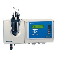
Rivo™ I Controller EN
59
Evoqua Water Technologies GmbH | W3T597263 Issue 01-0624
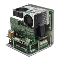
4 Carefully remove the metal cover of the HMI (Pos. 2).
5 Unscrew the four spacer bolts.
6 Grip the Rivo™ Com-Board carefully at the sides and
insert the connector strip precisely into the terminal
strips. Make sure that the connector strip is fitted cor-
rectly!
7 Tighten the four spacer bolts again by hand (to a
maximum torque of 0.7 Nm ± 0.15 Nm).
8 Refit the metal cover and screw tight again using the
four screws of the metal HMI cover.
9 Connect interface in accordance with the wiring dia-
gram.
10 Activate terminating resistor when installing at the
end of the bus.
11 Fit the housing cover again and tighten by hand (to a
maximum torque of 0.7 Nm ± 0.15 Nm).
12 Reconnect the power supply.
13 Switch the Electronics Module on or reconnect the
power supply.
14 Configure the interface.
 Loading...