Installation
This section describes the installation of the DMP128, including:
• Mounting the DMP128
• DMP128 Models
• Hardware Configuration
• Rear Panel Features and Cabling
• USB Configuration Port (Front Panel)
• Front Panel Indicators
• Reset Actuator and LED
Mounting the DMP128
The 1U high, full rack width, 8.5-inch deep DMP128 Digital Matrix Processor can be:
• Set on a table,
• Mounted on a rack shelf,
• Mounted under a desk or tabletop.
For detailed mounting options and UL rack mounting guidelines, (see
MountingtheDMP128 on page165).
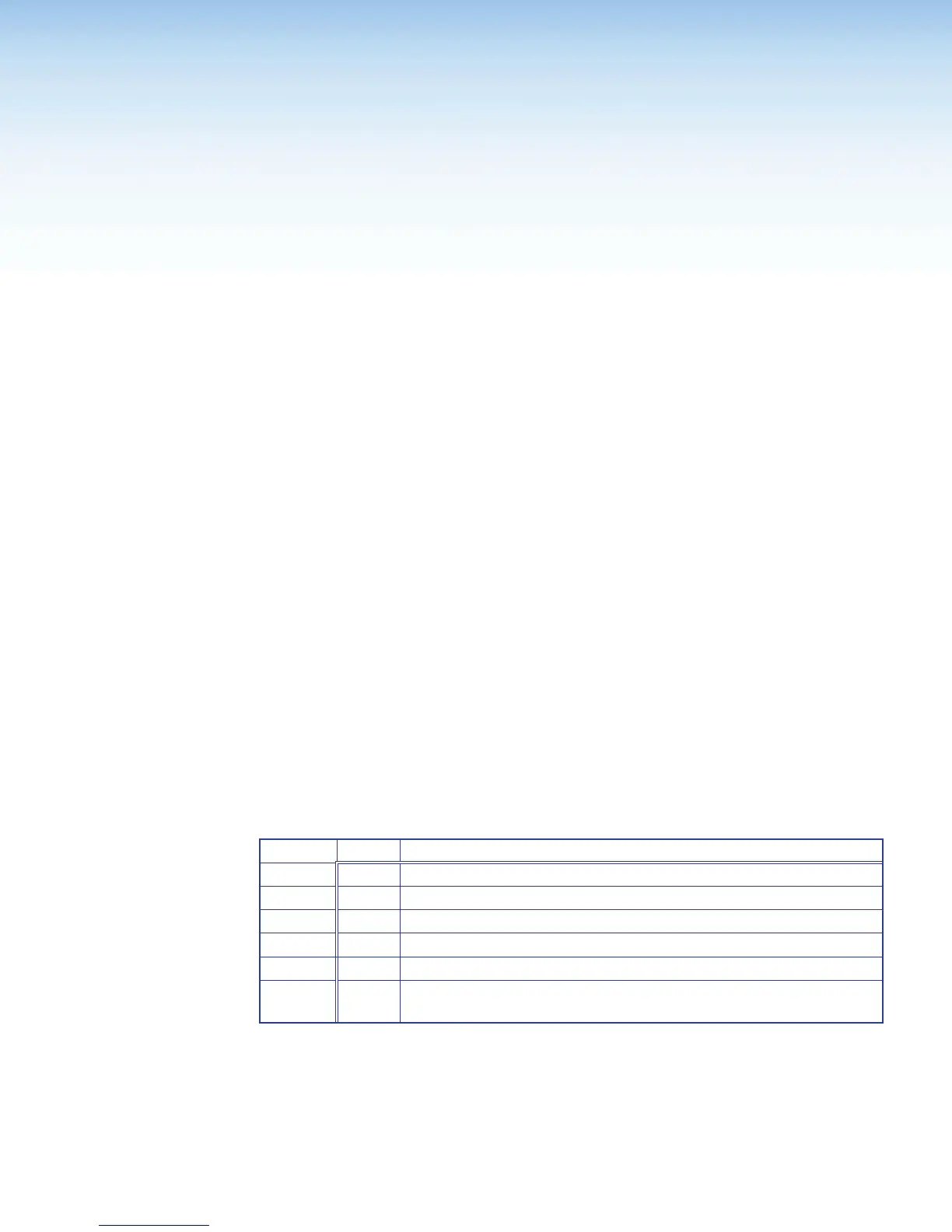
DMP128 Models
There are six models of the DMP128 available. Each model has a different feature set for
various applications.
DMP128 Model Matrix
The following feature matrix provides a breakdown of the various DMP128 model
variations. Where differences occur in operation, they are noted in the text.
Model Description
DMP128 12x8 ProDSP Processor
DMP128 C 12x8 ProDSP Processor with AEC
DMP128 AT 12x8 ProDSP Processor with Dante Interface
DMP128 C AT 12x8 ProDSP Processor with AEC, EXP Bus, and Dante Interface
DMP128 C P 12x8 ProDSP Processor with EXP Bus, AEC, and Telephone modem
DMP128 C PAT 12x8 ProDSP Processor with AEC, Telephone modem, EXP Bus, and
Dante Interface
Hardware Configuration
The DMP128 does not have physical controls for configuration or operation.
The DMP128 has several front and rear panel operational indicators and a rear panel
reset button for hardware resets outlined in the following pages.
DMP128 • Installation and Operation 5