4. Connect the EXP port of one unit to the EXP port of a second unit
using the included shielded (or similar) CAT 6 cable.
NOTE: The front panel EXP LED indicates device to device
connection and configuration status as follows:
• (non-AT models)
• Off — The unit is not connected to a second
DMP128.
• On — The unit is connected to another DMP128 and
configured as the primary unit.
• Blinking — The unit is connected to another
DMP128 and is currently configured as the secondary
unit.
• (AT Models)
• Off — Dante device is not responding.
• On — The EXP port is connected to a non-AT
DMP128 and configured as the primary unit.
• Blinking — The EXP port is not connected.
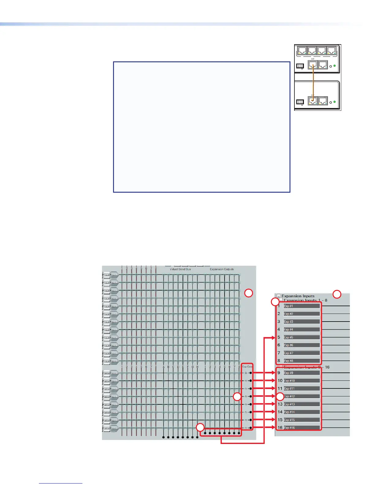
Using the Expansion Bus
After configuration and connection, the two units have 16x16 channels of bi-directional
audio communication.
• The expansion bus from the primary unit (see figure 49,
a
) sends audio to Expansion
inputs 1–16 of the secondary unit (see figure 49,
b
).
• At the same time, the expansion bus from the secondary unit sends audio to
Expansion inputs 1–16 of the primary unit.
0
1
2
3
4
5
6
EXP Bus Connection
Primary (1) to Secondary (2)
1
2
1A
1B
2A
2B
Figure 49. EXP Bus Connections
RESET
LAN
Tx Rx
RS-232
DIGITAL I/O
123 4 5
MIC
+48V
132
DMP 128 C
EXP
50/60 HZ
4
8
4
5768
910
11 12
678
9 10
11 12 13 14 15 16 17 18 19 20
O
U
T
P
U
T
S
2134
6578
100-240 ~ 0.6A
RESET
LAN
Tx Rx
RS-232
DIGITAL I/O
123 4 5
MIC
+48V
132
DMP 128 C AT
EXP
50/60 HZ
4
8
4
5768
910
11 12
678
9 10
11 12 13 14 15 16 17 18 19 20
O
U
T
P
U
T
S
2134
6578
34
12
DMP128 • Software Control 80