Using the Extron Expansion Bus with DMP128AT Devices
A DMP128PAT model can be connected to a non-AT model by the Expansion (EXP)
ports with the following exceptions:
• Two AT models cannot be connected together using their EXP ports.
• AT models are always the primary unit. The non-AT model must be set as the
secondary unit.
• The sixteen EXP outputs from the non-AT secondary unit connect to the AT primary
unit at inputs 41 through 56.
• The secondary DMP128 or DMP128C EXP inputs are routed as they normally
would be.
DMP128AT devices are set as the Primary unit by default. This setting cannot be
changed because the expansion bus primary and secondary selections in Device Settings
are not available on AT models (see Dante Network Audio Setup on page113). When
an AT device is connected to a non-AT device by the Expansion port, the non-AT device
must be set as the secondary unit.
To configure Expansion port connectivity using a DMP128AT:
1. Power on both units. Open DSP Configurator and connect Live to the non-AT
model DMP128.
2. From the menu, select Tools>ExpansionBus>Secondary
Unit.
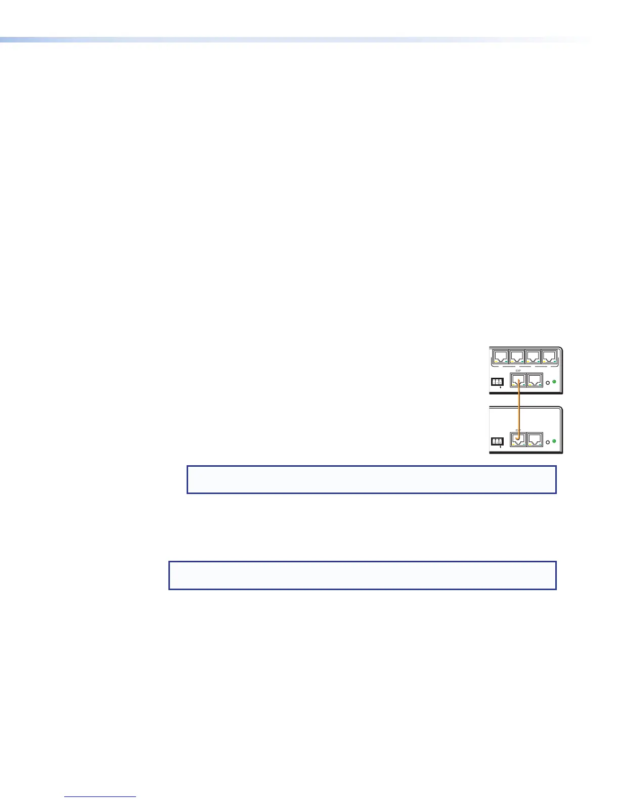
3. Connect the DMP128PAT EXP port to the non-AT model DMP128
EXP port using the included shielded one foot CAT6 or similar
CAT6 cable. When connectivity is established, the front panel EXP
LED on the primary unit (AT) lights solid and the EXPLED on the
secondary unit blinks.
In DSP Configurator, EXP bus channels appear as EXP Inputs
41through 56 on AT models, and 1 through 16 on non-AT models.
NOTE: When two non-AT models are connected, channels received on the
Expansion bus appear as Expansion Inputs 1 through 16.
Configuration of the EXP channels can be done at this time. You can also add additional
AT models to the digital audio network. Always make the Expansion port connection
between the two units before adding AT units to the digital audio network (see Dante
Network Audio Setup on page113).
NOTE: The Dante Controller software is required for configuration of the AT expansion
bus (see Dante Controller Software Installation on page113).
When connected to a non-AT device, all 56 receive channels of the DMP128AT still
appear on the Dante digital audio network. However, Expansion inputs 41 through 56 are
connected to the secondary (non-AT) device by the EXP bus, and are not operational on
the Dante audio network.
Viewing AT Channels with AT Meters
The AT meters allow the user to see the signal levels of any attached Dante device. See
View on page22 for information on accessing the meters.
A connected Dante device is selected and all active transmit and receive channel real-time
signal levels for that device are monitored.
RESET
LAN
Tx Rx
RS-232
DIGITAL I/O
123 4 5
MIC
+48V
132
DMP 128 C
EXP
50/60 HZ
4
8
4
5768
910
11 12
678
9 10
11 12 13 14 15 16 17 18 19 20
O
U
T
P
U
T
S
2134
6578
100-240 ~ 0.6A
RESET
LAN
Tx Rx
RS-232
DIGITAL I/O
123 4 5
MIC
+48V
132
DMP 128 C AT
EXP
50/60 HZ
4
8
4
5768
910
11 12
678
9 10
11 12 13 14 15 16 17 18 19 20
O
U
T
P
U
T
S
2134
6578
34
12
DMP128 • Dante Installation and Operation 125