USB Configuration Port (Front Panel)
A front panel configuration port uses an Extron USB A Male to USB Mini B Male
Configuration Cable, 26-654-06 for connection to a PC computer USB port.
The USB 2.0 port uses a mini type-B connector to connect to a host computer for
control. The DMP128 USB driver must be installed prior to using the port (see Installing
the USB Driver on page15).
NOTE: The DMP128 appears as a USB peripheral with bi-directional
communication. The USB connection is used for software operation (see
Windows-based Program Control on page13), and SIS control (see SIS
Programming and Control on page129).
Front Panel Indicators
DMP 128
DIGITAL MATRIX PROCESSOR
CONFIG
1
CLIP
SIGNAL
INPUTSOUTPUTS
1
CLIP
SIGNAL
2 3 4 5 6 7 8 9 10 11 12 2 3 4 5 6 7 8
EXP LAN
ACTIVITY
cda Ç É
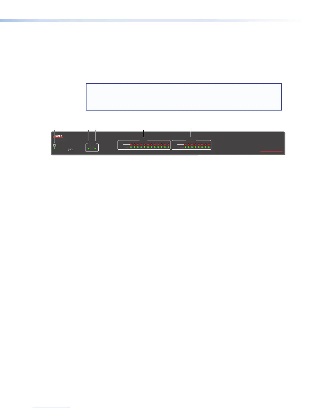
Figure 7. DMP128 Front Panel
a
Power LED — The power indicator blinks during power-up and firmware uploads,
and lights solid when the DMP128 is operational.
b
Activity Indicators — Two green LEDs labeled EXP (
Ç
)
for the expansion audio port
and LAN (
É
)
for the standard Ethernet port
Ç
(non-AT models)
Off — The unit is not connected to a second DMP128.
On — The unit is connected to another DMP128 and configured as the primary
unit.
Blinking — The unit is connected to another DMP128 and is currently
configured as the secondary unit.
Ç
(AT Models)
Off — Dante device is not responding.
On — The EXP port is connected to a non-AT DMP128 and configured as the
primary unit.
Blinking — The EXP port is not connected.
É Indicates activity on the corresponding rear panel Ethernet port connection.
c
Input Indicators — Stacked red (signal clipping) and green (signal present) LEDs for
inputs 1 through 12 . Each stack represents one input channel.
The green signal LED varies in brightness corresponding to the real-time input or
output signal level (see item
d
, below). It begins to light at – 60dBFS increasing
in steps to full intensity as the signal level increases. When the signal level reaches
– 3dBFS or above, the red clipping LED lights and remains lit as long as the signal
remains above – 3dBFS. When it falls below that level, the red LED remains lit for 200
milliseconds, after which the display resumes real-time monitoring of the signal level.
d
Output Indicators — Stacked red (signal clipping) and green (signal present) LEDs
for outputs 1 through 8. Each LED stack represents one output channel.
DMP128 • Installation and Operation 9