h EXP port connector — One RJ-45 jack for one additional DMP128 connection.
The EXP connector has a green LED to indicate proper connection to an active
expansion network and a yellow LED that blinks to indicate data activity.
RESET
LANEXP
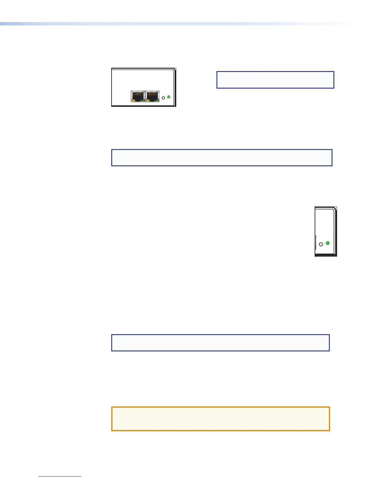
Figure 6. EXP and LAN Connections
i LAN connector — A standard RJ-45 jack (see above) accepts a standard Ethernet
cable for network connection. The control system and DMP128 must be connected
to the same network.
NOTE: To connect the DMP128 directly to a computer Ethernet port, use a
crossover Ethernet cable.
• A yellow (ACT) LED indicates data activity on the connection.
• A green (Link) LED indicates the jack is connected properly to the network.
See SIS Programming and Control on page129 for additional information on
Ethernet cabling.
j Reset button and LED indicator — The reset button returns the DMP128
to different tiers of default states and can place the unit into an event
recording mode for troubleshooting. When using the reset function, the LED
flashes to signify the different tiers (see DMP128 Hardware Reset Modes
on page169). When not in reset mode, the LED operates as a power
indicator, duplicating the front panel LED operation.
k AT connections (AT models only) — Four RJ-45 jacks for Ethernet
connection form a 4-port Gigabit switch that interfaces with the AT bus. The AT
port expansion bus uses the Dante protocol for digital media networking allowing
connection of multiple DMP128AT models to form a larger matrix.
The AT bus supports 56 channels of audio input (Rx) per DMP128AT. Output
channel support (Tx) includes the eight line outputs, eight virtual returns (post
processing), and eight expansion outputs for a total of 24 channels. Audio from an
AT port is placed on a network and the audio channels assigned to the network
are available to any Dante-compatible device on the network, such as another
DMP128AT.
NOTE: The Dante Controller software is required for configuration of the AT
expansion bus (see Dante Controller Software Installation on page113).
l Telephone connections (P models only) — These optional connections provide
telephony access.
The POTS interface provides two RJ-11 telephone jacks to connect to the incoming
phone line (LINE) and the telephone (PHONE).
The telephone interface follows all applicable US and International standards.
ATTENTION: For telephone and network cabling, to reduce the risk of fire,
use a minimum conductor size of 26 AWG, UL Listed or CSA Certified
Telecommunication Line Cord.
RESET
NOTE: A one foot shielded CAT6 cable
is provided for the EXP connection.
DMP128 • Installation and Operation 8