e Mono output connectors — Four 6-pole 3.5 mm captive screw connectors provide
up to eight balanced or unbalanced connections for mono line level output signals.
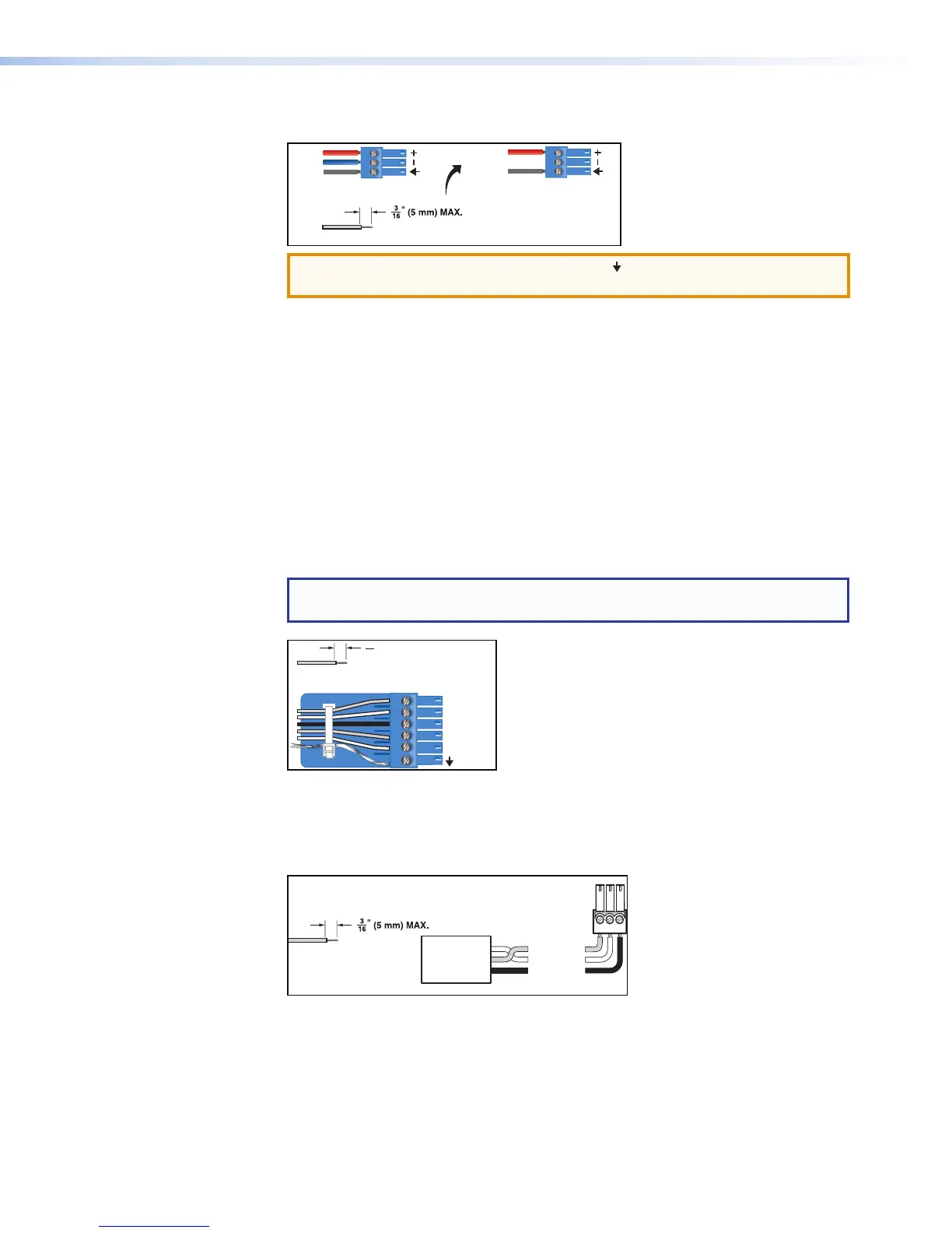
Audio Output Wiring
Audio Input Wiring
Unbalanced Output
Tip
Sleeve
NO Ground Here
Balanced Output
Tip
ve
Ring
Unbalanced Input
Tip
Sleeve
Balanced Input
Tip
Sleeve
Ring
Do not tin the wires!
Do not tin the wires!
ATTENTION: Connect the sleeve to ground ( ). Connecting the sleeve only to
a negative(– ) terminal will damage the audio output circuits.
Figure 3. Output Connector Wiring
f Digital I/O output connectors — Four 6-pole 3.5 mm captive screw connectors
each provide five configurable digital input or output ports allowing connection of up
to twenty various devices such as motion detectors, alarms, lights, LEDs, buttons,
photo (light) sensors, temperature sensors, and other devices.
Digital I/O ports monitor or drive TTL level digital signals. The inputs can be configured
to operate in one of two modes: digital input or digital output. In output mode, the
device can source up to 250mA at +5 V. In Input mode, voltages greater than 1 V
indicate a logic ‘high’ signal while voltages less than 1 V indicate a logic ‘low’.
All digital I/O ports are tied to a common ground (one common ground for each
6-pole connector), but can be individually configured to operate in one of two modes:
digital input or digital output
NOTE: These ports can be configured via the DSP Configurator (see
DigitalI/OPorts on page88).
Do not tin the wires!
(5 mm) MAX.
16
1
2
3
4
5
Figure 4. Digital I/O Wiring
g RS-232 connector — One 3-pole 3.5 mm captive screw connector, labeled RS-232,
for bi-directional RS-232 (±5V) serial control. Default baud rate is 38400. The RS-232
port is not intended to be used for configuring the DMP128.
Receive (Rx)
Transmit (Tx)
Ground (G)
Bidirectional
RS-232
Device
Ground ( )
Receive (Rx)
Transmit (Tx)
G
Do not tin
the wires!
Figure 5. RS-232 Wiring
DMP128 • Installation and Operation 7