When bypassed, the graph displays the current filter curve as a dotted line. When bypass
is disengaged, the current filter curve is displayed as a solid line.
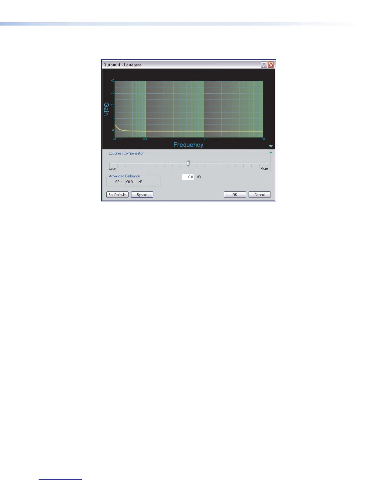
Figure 34. Loudness Dialog Dialog box
The Loudness dialog box contains the following elements:
1. Graph — Displays the compensation curve currently applied to the signal. These
curves are read-only, and are not adjustable from the graph.
2. Loudness Compensation slider — From a center zero-point, the user can slide to
the left for less loudness compensation (filter curve is reduced), or to the right for more
(filter curve is increased). The slider position is translated into adB value, displayed in
the compensation readout box contained in the Advanced Calibration section. The
slider has a 48dB (
±
24dB) range.
3. Advanced Calibration — Provides a value that corresponds to the position of the
compensation adjustment slider. The SPL box displays the summed value of the
slider and the preceding trim control.
Calibrating Loudness
The user can fine-tune the amount of loudness compensation using the compensation
adjustment slider and adjusting “by ear,” or by measuring SPL levels in a particular room,
then using the slider to adjust the loudness filter relative to the SPL of the room and
system gain structure.
Before calibrating loudness, set up the system gain structure (see Optimizing Audio
Levels on page100). A pre-recorded track of pink noise or pink noise from a signal
generator is preferable for this purpose. Program material can also be used (using familiar
material is recommended).
If using a signal generator, set it to output – 10dBu, then set the input gain of the
DSPConfigurator so the input meter reads – 20dBFS. If using a recorded source, the
pink noise should be recorded at – 20dBFS and the player output level setting control set
to maximum, or 0dB of attenuation. For program material, set the input level to meter at
approximately – 15dBFS, with peaks safely below 0dBFS.
DMP128 • Software Control 59