4 Electrical installation
28 Festo – GDCP-CMMP-M0-HW-EN – 1511c – English
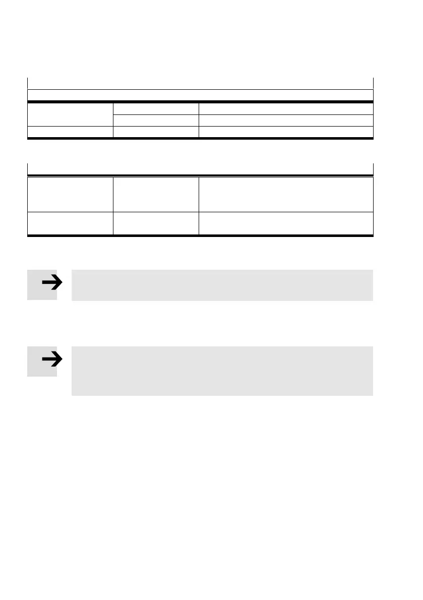
The power supply cables for the power end stage are alternatively connected to the following terminals:
Power end stage supply
Observe instructions in chapter è 4.8.5
AC supply L, N for single-phase motor controllers
L1, L2, L3 for three-phase motor controllers
DC supply ZK+, ZK–
Tab. 4.1 Connection of power supply cables
Motor temperature switch
PTC or N/C contact/
N/O contact
1)
(e.g. KTY81)
MT+, MT–;
[X6]
if this is carried together with the motor phases in
one cable
Analogue
temperature sensor
1)
MT+, MT–;
[X2A] or [X2B]
1) EMMS-AS motors have a PTC
Tab. 4.2 Connection of the motor temperature switch
Note
Temperature sensors must be sufficiently isolated from the motor winding.
The connection of the encoder/resolver via the Sub-D plug connector to [X2A] or [X2B] is roughly shown
diagrammatically in è Fig. 4.1,
è Fig. 4.2 and è Fig. 4.3.
Note
If the polarity of the operating voltage connections is reversed, or if the operating
voltage is too high or the operating voltage and motor connections are reversed, the
motor controller CMMP-AS-...-M0 will be damaged.
 Loading...


