A. Technical appendix
A−14
Festo P.BE−CPEA−CL−EN en 0711a
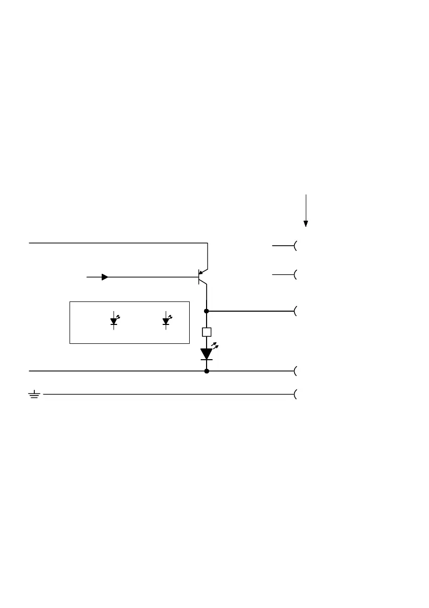
A.3 Internal structure of the outputs
A.3.1 Internal structure type CP−A04−M12−CL and CP−A08−M12−EL−Z
Name for ports: E.g.: 1 for CL modules, x1 for EL modules
Pin 1
Pin 2
Pin 4
Pin 3
1
6
5
2
24V
0V
Pin 5
4
3
1
Actuator connection
1: n.c.
2: Port x1, (x3): x+1, (x+3)
Port x2, (x4): n.c. (not connected)
3: 0V
4: Port x1: Ox
Port x3: Ax+2
5: FE
2 PLC/IPC Ox (e.g. via fieldbus)
3 Diagnosis
Short circuit/overload
Load voltage failure.
Undervoltage in load supply
4 Green LED (PL)
5 Red LED (fault symbol)
6 Yellow LED (output)
Ox = Output x
Fig.A/4: Internal structure type CP−A04−M12−CL and CP−A08−M12−EL−Z