5. Output module type CP−A08−M12−EL−Z
5−4
Festo P.BE−CPEA−CL−EN en 0711a
5.1.1 Display and connecting elements
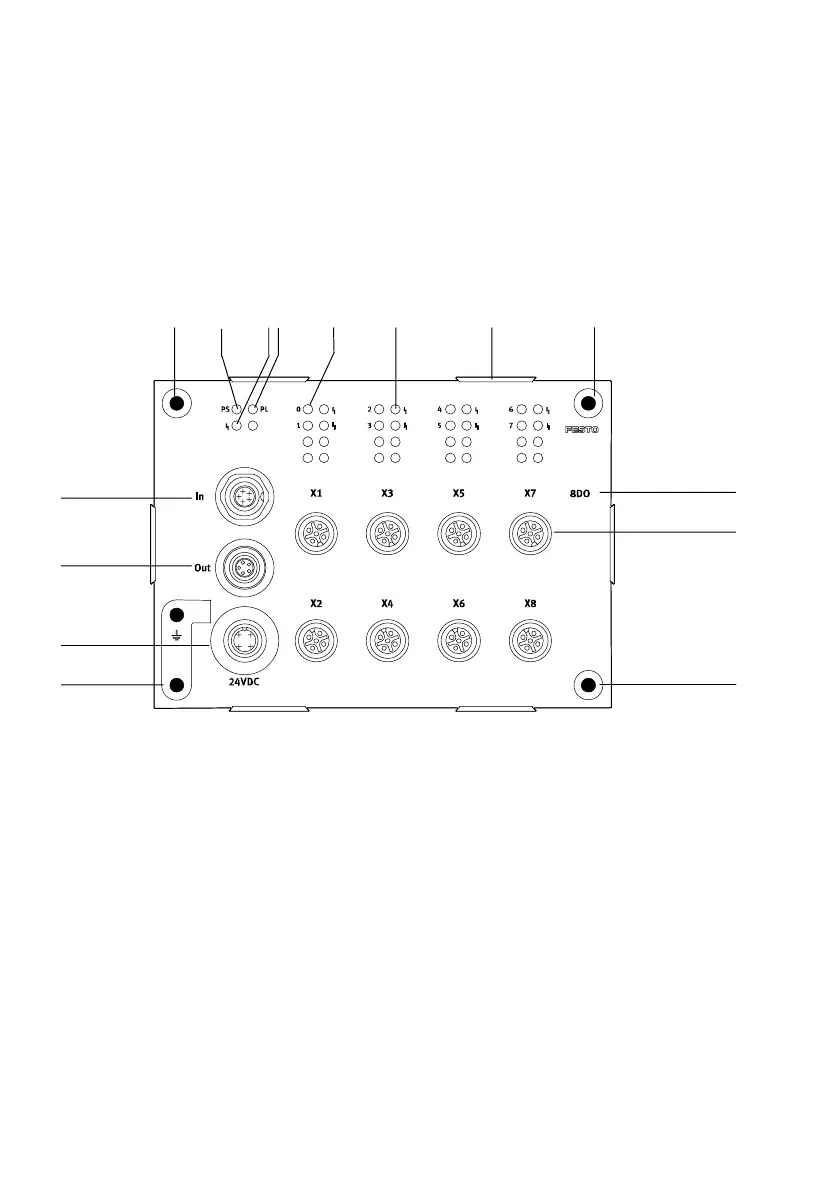
The following diagram shows the display and connecting
elements of output module CP−A08−M12−EL−Z.
1
2
3
4
5
6
78 aJ
aB
aA
aC
9 5
5
1
CPI connection incoming
2 CPI connection continuing
3 Load supply for outputs
4 Fastening hole with earth connection
5 Fastening holes
6 Status LED CP communication
(PS, green)
7 Status LED output (module) short
circuit/overload (red)
8 Status LED
Load supply (PL, green)
9 Status LEDs for outputs
(status display, yellow)
aJ Status LED output (channel) short
circuit/overload (red)
aA Mounting for inscription label holder
(type: ASCF−H−E2)
aB Module designation
aC 8 outputs (1 output per socket)
Fig.5/1: Display components and connecting elements type CP−A08−M12−EL−Z