5. Output module type CP−A08−M12−EL−Z
5−10
Festo P.BE−CPEA−CL−EN en 0711a
5.4.2 Connecting the actuators
For connecting the actuators, use plugs and cables with M12
union nut from the Festo range (see Appendix A.6).
· Tighten the plugs with the aid of the union nut in order to
prevent unintentional loosening, e.g. due to shock.
· Seal unused connections with the protective caps sup
plied. Only in this way can you comply with protection
class IP65.
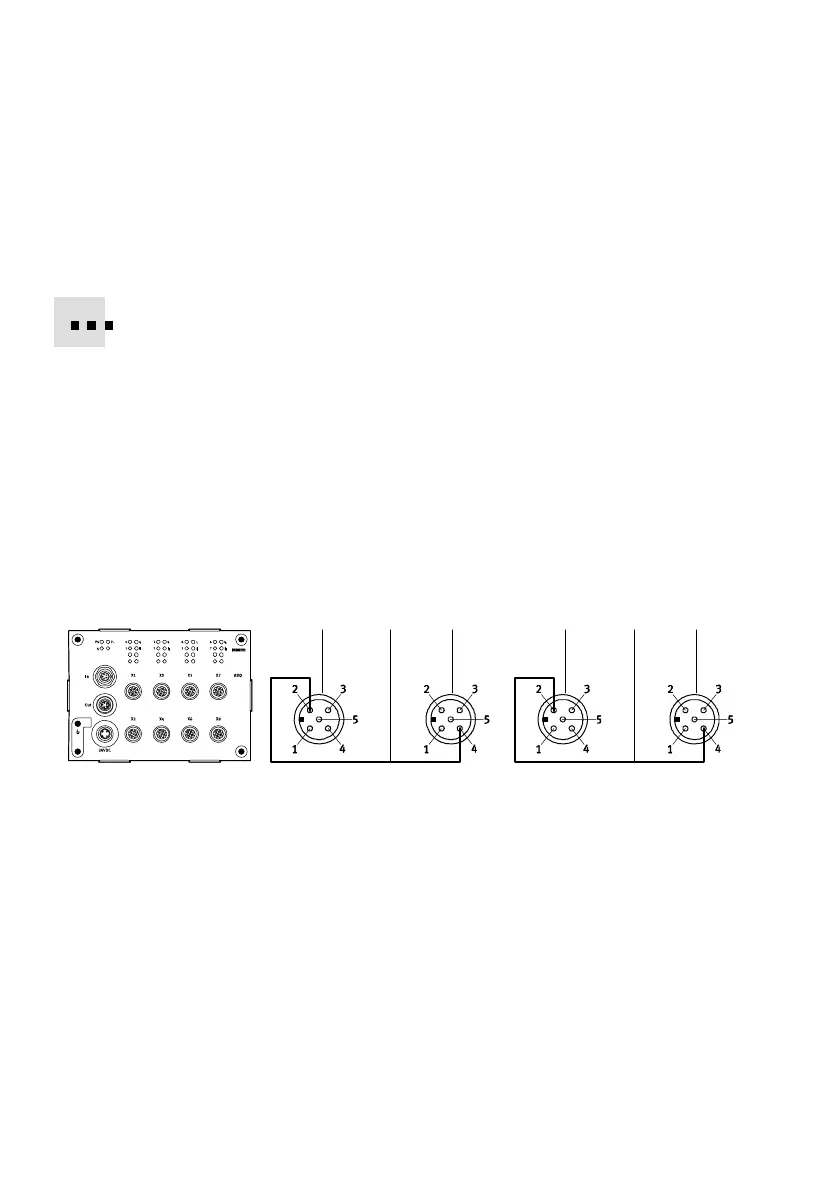
Pin allocation
The following diagram shows as an example the pin allocation
of the actuator connections on the CPI output module.
1 25 3 45
Port x1 Port x2
Port x3
Port x4
1 Pin allocation
Port x1
1: n.c.
2: Ax+1
3: 0V
4: Ax
5: FE
2 Pin allocation
Port x2
1: n.c.
2: n.c.
3: 0V
4: Ax+1
5: FE
3 Pin allocation
Port x3
1: n.c.
2: Ax+3
3: 0V
4: Ax+2
5: FE
4 Pin allocation
Port x4
1: n.c.
2: n.c.
3: 0V
4: Ax+3
5: FE
5 Internal connection in module n.c.= (not connected)
AX = output x
Fig.5/5: Pin allocation type CP−A08−M12−EL−Z