3. Output module type CP−A04−M12−CL
3−4
Festo P.BE−CPEA−CL−EN en 0711a
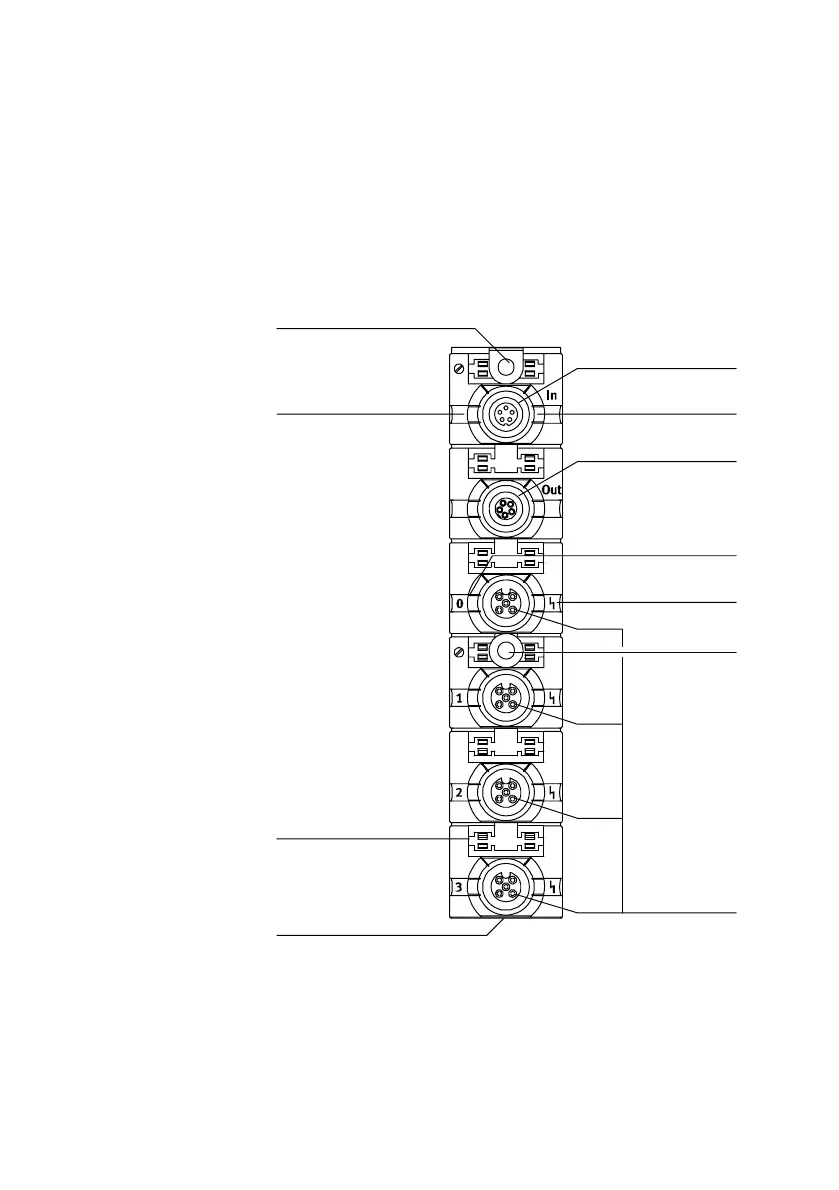
3.1.1 Display and connecting elements
The diagram below shows the display and connecting
elements on the output modules.
1 CP connection
incoming
2 Continuing CP
connection
3 Status LED load
supply (PL, green)
4 Status LEDs for out
puts (status display,
yellow)
5 Status LED short
circuit/overload at
outputs (red)
6 Status LED CP
communication
(PS, green)
7 Actuator connections
8 Name plate
9 Groove for identifica
tion signs, 6x (type
IBS 8x20)
aJ Mounting hole
aA Fastening hole with
earth connection
1
2
3
4
5
6
7
8
9
aJ
PS
PL
aA
Fig.3/1: Display and connecting elements type CP−A04−M12−CL