3. Output module type CP−A04−M12−CL
3−7
Festo P.BE−CPEA−CL−E N en 0711a
3.3.1 Connecting the actuators
For connecting the actuators, use plugs and cables with union
nut and M12 thread from the Festo range (see Appendix A.6).
· Tighten the plugs with the aid of the union nut in order to
prevent unintentional loosening, e.g. due to shock.
· Seal unused connections with the protective caps sup
plied. Only in this way can you comply with protection
class IP65/IP67.
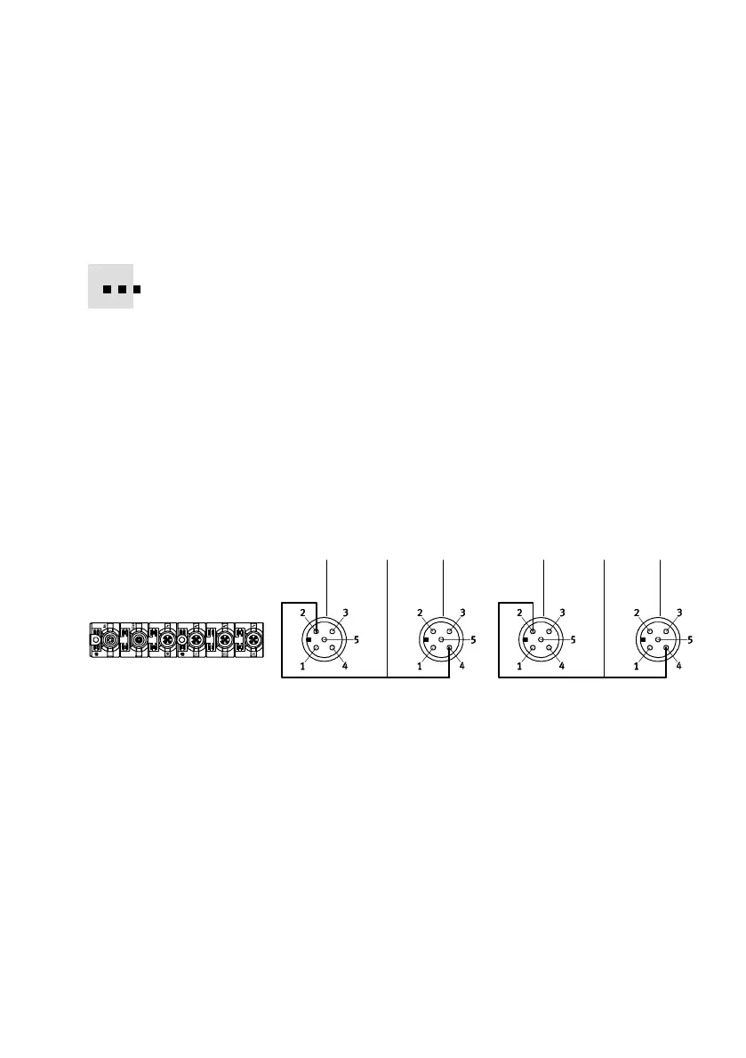
Pin allocation
The following diagram shows as an example the pin allocation
of the actuator connections on the CPI/CP output module.
1 25 3 45
Port 1 Port 2 Port 3 Port 4
1 Pin allocation
Connection 1
1: n.c.
2: Ax+1
3: 0V
4: Ax+0
5: FE
2 Pin allocation
Connection 2
1: n.c.
2: n.c.
3: 0V
4: Ax+1
5: FE
3 Pin allocation
Connection 3
1: n.c.
2: Ax+3
3: 0V
4: Ax+2
5: FE
4 Pin allocation
Connection 4
1: n.c.
2: n.c.
3: 0V
4: Ax+3
5: FE
5 Internal connection in module n.c.= (not connected)
AX = output x
Fig.3/3: Pin allocation type CP−A04−M12−CL