2. Input modules types CP−E08−M...−CL and CP−E16−KL−CL
2−10
Festo P.BE−CPEA−CL−EN en 0711a
Pin assignment (PNP inputs)
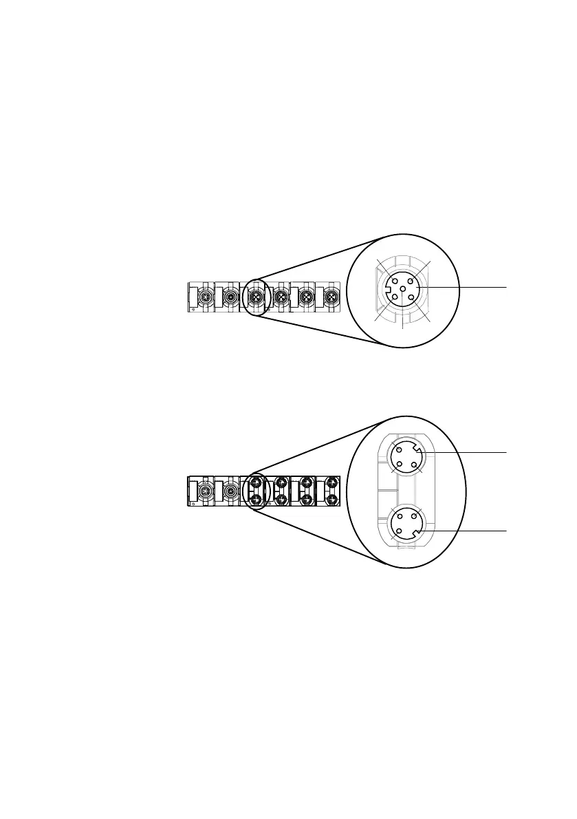
The following diagrams show as an example the pin assign
ment of the sensor connections of the different CP input
modules.
Pin assignment
1 1: 24V
2: Ix+1
3: 0V
4: Ix+0
5: Ground terminal
Ix = Input x
1
01
23
45
67
Out
PC
In
01
4
1
3
2
5
Fig.2/5: Pin assignment type CP−E08−M12−CL
Pin assignment
1 1: 24V
4: Ix+1
3: 0V
2 1: 24V
4: Ix+0
3: 0V
Ix = Input x
1
4
3
1
Out
PC
In
0
2
4
6
3
5
7
1
0
1
4
3
1
2
Fig.2/6: Pin assignment type CP−E08−M8−CL