1. Installation
1-22
Festo P.BE-CPX-PNIO-E N en 1407c English
Note – pin a l l ocation port TP2
Deactivation of the crossover detection ch anges the pin
allocation of the outgoing port TP2 to “crossover”.
Choose the network line (patch cable or crossover cable)
depending on the pin allocation of the devices connected
to TP2 (I/O devices) Fig. 1/4:
– crossover cables with the same allocation of the ports
– patch cable with different allocation of the ports.
•
Make sure that the function “Autonegotiation/Autocros-
sover” is deactivated in your control software before pla-
cing the system in operation (see section 2.6.4).
•
If necessary, the function “ Autonegotiation/Autocrossov-
er” must also be deactiva ted on the hardware-si de, in the
basic setting of your controller (PLC) or switches or
routers in between: ch eck the port settings for this pur-
pose.
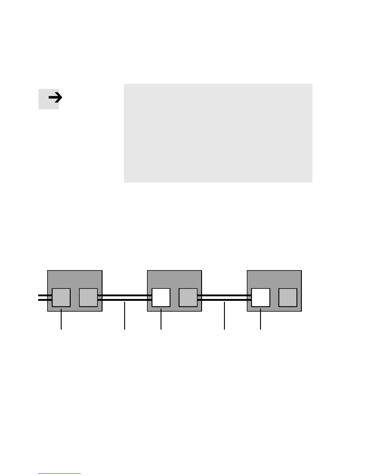
PLC or switch I/O device I/O device
123 3
TP1 TP2 TP1 TP2 TP1 TP2
2
1
Switch port, e.g. of the PLC
(“crossover” pin allocation)
2
Terminal port of an I/O device
3
Patch cable
Fig. 1/4: Wiring of the I/O devices for “Fast start-up” with deactivated “crossover” de-
tection or “autonegotiatio n” (configuration example)