Do you have a question about the FISCHER FT90 and is the answer not in the manual?
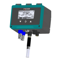
The FT90 is a humidity and temperature measuring device from the PRO-LINE® series, with an optional differential pressure measurement capability. It is designed for use in neutral gaseous media and is available in versions suitable for potentially explosive areas (zone 2 for gases and vapours, and zone 22 for dusts).
The FT90 measures temperature and humidity using a sensor chip with a digital I2C bus interface. The analog measurement data is digitally converted and linearized. This data is then processed by integrated electronics and can be displayed, output as an analog signal, or sent via up to four switch outputs or an optional Modbus output.
For pressure measurement, the device utilizes a piezo-resistive sensor element capable of measuring overpressure, negative pressure, or differential pressure. This sensor features a silicon membrane equipped with a measuring bridge. When a pressure difference occurs, the membrane deflects, causing a resistance change in the measuring bridge. This change is evaluated by the integrated electronics and transformed into a display, analog output, or switch outputs, or transmitted via the optional Modbus output.
The device can be configured for 2-channel (Temperature/Humidity) or 3-channel (Pressure/Temperature/Humidity) operation.
General:
Input Variables:
Differential Pressure (Asymmetric Measuring Ranges): Ranges vary from -20 to +80 Pa up to 0 to 250 mbar (0 to 25 kPa). Overload capacities range from 100 mbar to 2.5 bar, and bursting pressures from 200 mbar to 5 bar, depending on the specific measuring range and sensor type (A or B). Some ranges offer increased overload and bursting pressure capability.
Differential Pressure (Symmetric Measuring Ranges): Ranges vary from -25 to +25 Pa up to -250 to +250 mbar (-25 to +25 kPa). Overload capacities range from 100 mbar to 2.5 bar, and bursting pressures from 200 mbar to 5 bar, depending on the specific measuring range and sensor type.
Output Sizes (Analog Outputs):
Switch Outputs:
Measuring Accuracy:
Digital Interfaces:
Auxiliary Energy:
Operating Conditions:
Construction Design:
Assembly: The device is designed for installation on assembly plates or wall surfaces and comes with a pre-mounted 35 mm plastic assembly rail. It can also be mounted to a 35 mm top-hat rail. While calibrated for vertical installation, the installation position is arbitrary, with offset correction available for non-vertical positions. The enclosure protection type IP65 is guaranteed only with a suitable power supply cable.
Electrical Connections: Connections must be made by authorized and qualified personnel, observing national and international electro-technical regulations. The system must be disconnected from the mains before connecting the device. Consumer-adapted fuses should be installed, and connectors should not be strained. The outer ground connection must always be connected to protective potential equalization.
Operation in Explosive Areas: For ATEX models, specific regulations (e.g., DIN EN 60079) and personnel training are required. A CE-conform mains adapter with a slow 200 mA fuse is mandatory. The housing of ATEX devices must not be opened in potentially explosive areas.
User Interface: The device features a graphical display with RGB backlighting, allowing for various color backgrounds and color changes to indicate when limits have been overstepped. Navigation is via a keyboard with "Page down," "Call up menu," and "Page up" buttons. The menu structure is hierarchical, with up to five levels. Passwords are used to control access to configuration settings.
Configuration: Parameters can be modified via the device's menu or more comprehensively using the inTouch® PC software via the USB interface. Quick access menus allow for rapid changes to language, measuring point designation, unit, measuring range, and damping.
Operating Modes: The device automatically starts in operating mode after activation. Pressing the "Call up menu" button switches to configuration mode, where all parameter changes have an immediate effect on device operation.
Analog and Switch Outputs: Analog outputs can be configured for various signal types (current or voltage) and assigned to specific measuring channels. Switch outputs can be assigned to channels, with configurable activation/deactivation points, delays, and functions (normally open/closed).
Modbus RTU Interface: Devices with a Modbus interface can be connected to a Modbus RTU network as a slave. Star-shaped networks are not allowed. A 120 Ω bus termination resistor is recommended for fault-free data transmission.
General Maintenance: The instrument is maintenance-free, but regular inspections are recommended for reliable operation and long service life. This includes checking the function with downstream components, leak-tightness of pressure connection lines, and electrical connections. Test cycles should be adapted to operating and environmental conditions.
Transport: The measuring device must be protected against impacts and should be transported in its original packaging or a suitable transport container.
Service and Disposal: Defective devices should be sent to the manufacturer's repair department. When handling dismantled devices, precautions must be taken against process media residues that could be hazardous. The device and packaging materials should be disposed of in compliance with national waste and recycling guidelines.
Firmware Updates: Firmware updates can be performed via the USB interface, but for ATEX devices, this must be done outside potentially explosive areas.
Password Management: The device includes user management with different access levels (User 1, 2, 3, Administrator). Passwords can be changed, and an administrator can reset all passwords to the factory setting. A timeout function can automatically log out users after a defined period.
| Brand | FISCHER |
|---|---|
| Model | FT90 |
| Category | Measuring Instruments |
| Language | English |