2 | Product and functional description FISCHER Mess- und Regeltechnik GmbH
10/108 BA_EN_FT90
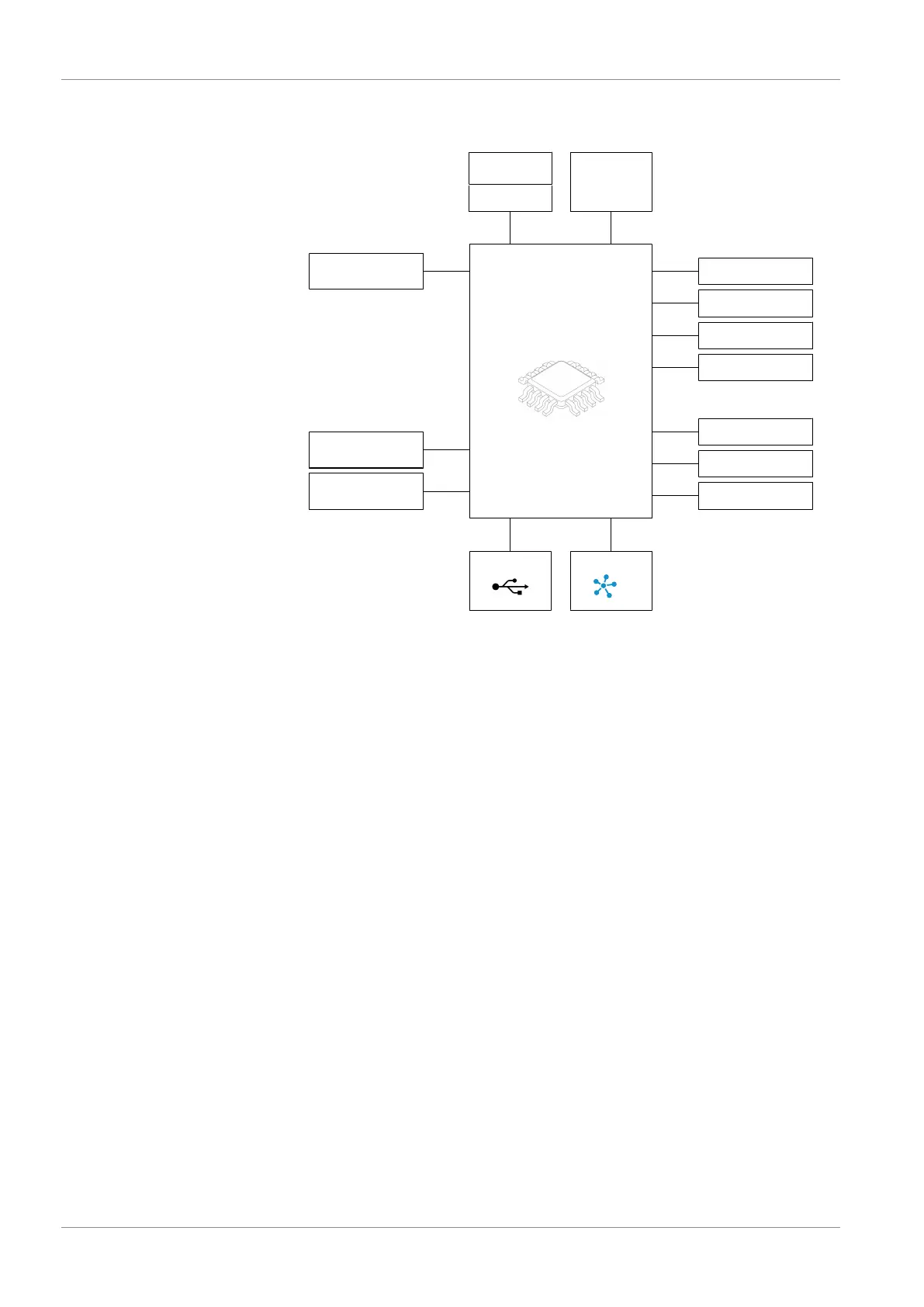
2.3 Function diagram
Sensor 2
Display
þ û ÿ
Analog output 1
Switch output 1
Switch output 2
Switch output 3
Switch output 4
Temperature
Power
supply
24 V AC/DC
USB OTG RS485
Analog output 2
Sensor 3
Humidity
µC
Options
Sensor 1
Differential pressure
Option
Analog output 3
Channel 1
Channel 2
Channel 3
Option
Fig.1: Function diagram
2.4 Design and mode of operation
Temperature and humidity measurement
The temperature and humidity measurement is based on a sensor chip with a
digital I2C bus interface. The analog measurement data is digitally converted
and linearised. The transmitted data is evaluated by the integrated electronics
and is transformed into a display, analog output, and up to four switch outputs
or output via the optional Modbus output.
Pressure measurement
The pressure measurement is based on a piezo-resistive sensor element that is
suitable for measuring overpressure, negative pressure, and differential pres-
sure. The pressures to be compared have a direct effect on a silicon membrane
equipped with a measuring bridge.
When the pressure is equal, the measuring membrane is in its idle state. If a
pressure difference occurs, the membrane is deflected and a resistance change
takes place on the attached measuring bridge. This change is evaluated by the
electronics integrated into the device and is transformed into a display, analog
output, and up to four switch outputs or is output via the optional Modbus out-
put.