5 | Operation FISCHER Mess- und Regeltechnik GmbH
84/108 BA_EN_FT90
5.5.4.4 Colour change assignment
Path: \Configuration\Display\Col.ch. assignment
Level: 3
Col.ch. assignment
1 2 3 4
Channel 1
Channel 2
Channel 3
Back
H
G
U
G
E
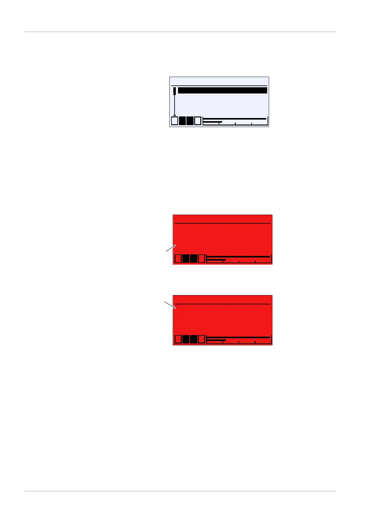
Fig.126: Colour change assignment
This menu is used to define the channel that controls the colour change. If mul-
tiple channels are selected, the colour change takes place once one of the
channels triggers a colour change. The triggering channel is marked with a dot.
The indicators are deleted once the green range is entered again.
Example Two channels are displayed on the operating display. First, channel 2 triggers a
green-red colour change. Shortly after, the same colour change is triggered by
channel 1.
Measurement point 1
C1
C2 %rH
Pa21.,4
Pa54,,,.6
1 2 3 4
°C
U
•
Triggering channel
Green-red colour change on channel 2
Measurement point 1
C1
C2 %rH
Pa28.2
Pa54.6
1 2 3 4
°C
U
•
•
Triggering channel
Event 1:
Green-red colour change on channel 1Event 2:
Fig.127: Display of measured values (colour change)