FISCHER Mess- und Regeltechnik GmbH Operation | 5
BA_EN_FT90 77/108
5.5.2 Analog output
The number of analog outputs depends on the version.
2-channel version 2 analog outputs
3-channel version 3 analog outputs
Path: \Configuration\Analog output
Level: 2
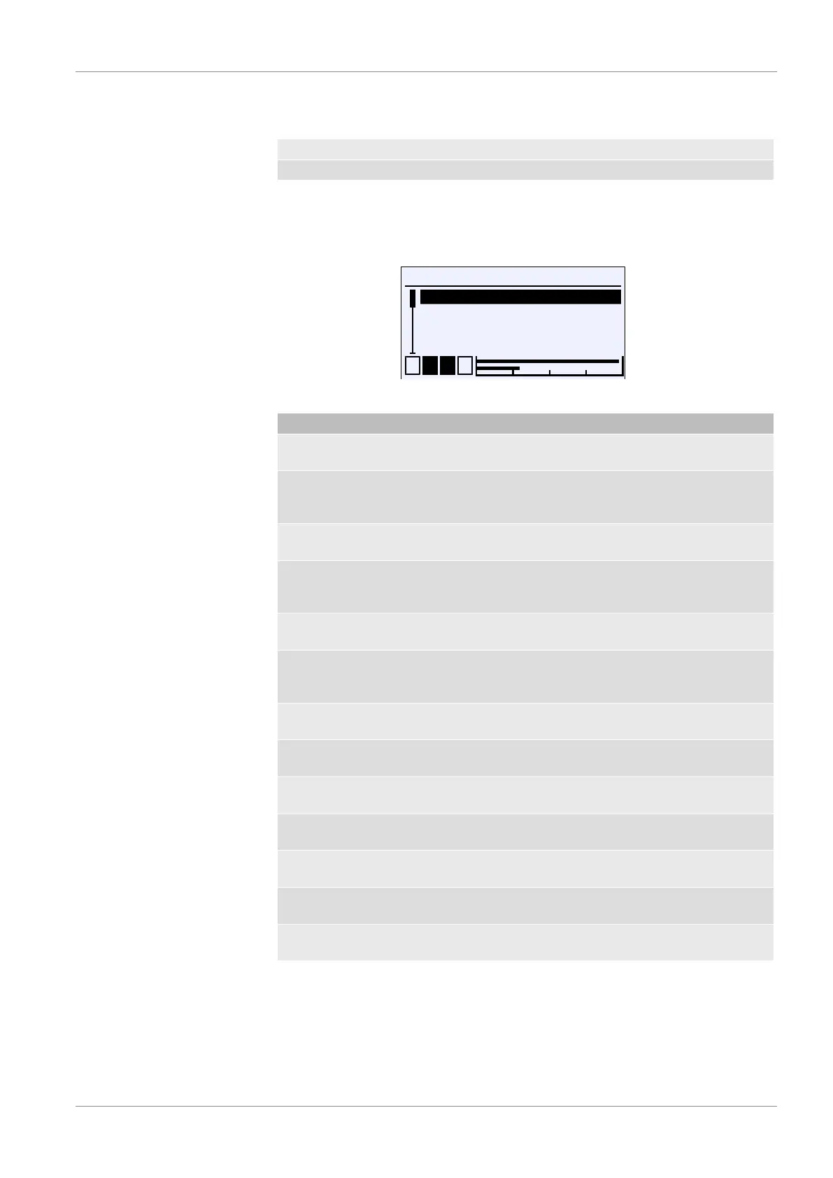
\...\Analog output
1 2 3 4
An.output 1 type
An.output 1 assignmnt
An.output 2 type
An.output 2 assignmnt
A
A
U
A
A
Fig.113: Analog output
Menu name Description
An.output 1 type A This menu is used to define the output
signal for output 1.
An.output 1 assignment A The measuring channel to which out-
put 1 is assigned is defined in this
menu.
An.output 2 type A This menu is used to define the output
signal for output 2.
An.output 2 assignment A The measuring channel to which out-
put 2 is assigned is defined in this
menu.
An.output 3 type A This menu is used to define the output
signal for output 3.
An.output 3 assignment A The measuring channel to which out-
put 3 is assigned is defined in this
menu.
Limit I min. Parameter for the lower limit of the cur-
rent output
Limit I max. Parameter for the upper limit of the
current output
I-error signal Parameter for the error signal of the
current output
Limit U min. Parameter for the lower limit of the
voltage output
Limit U max. Parameter for the upper limit of the
voltage output
U error signal Parameter for the error signal of the
voltage output
Back E This is the menu exit point. It takes you
back to the configuration menu.
The parameters for the type and assignment work in the same way for all chan-
nels. Consequently, the parameters are explained below using channel 1 as an
example.
This also applies for limit parameters, which are explained using the current sig-
nal as an example. If the signal type is changed, the entered parameters for the
previous signal are retained.