3 | Assembly FISCHER Mess- und Regeltechnik GmbH
20/108 BA_EN_FT90
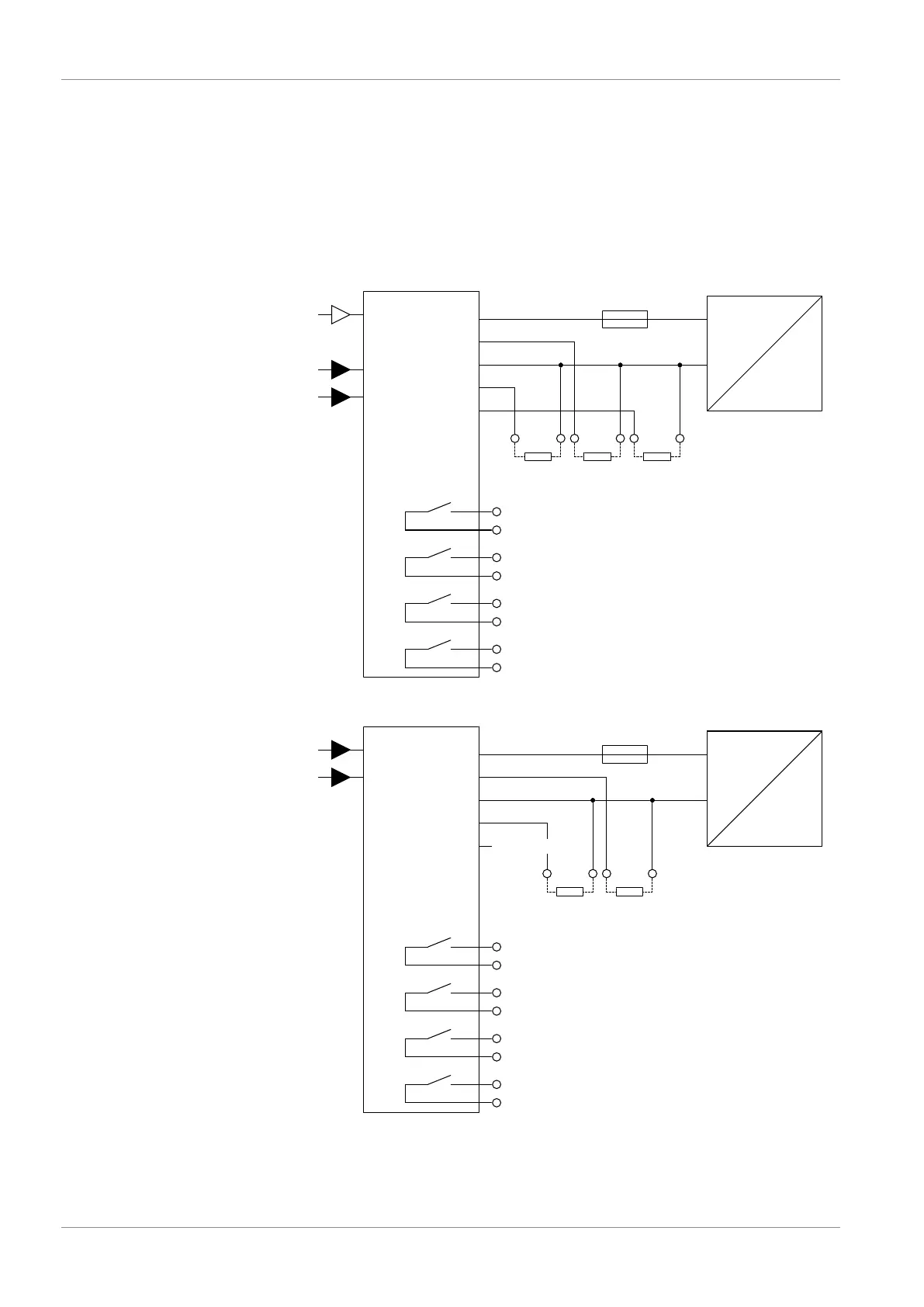
3.4.3 Devices with switching and analog outputs
3.4.3.1 Circuit
The device is connected in a 3-wire circuit as described below. The admissible
load/impedance is stated in the technical data. The connection is performed us-
ing a prefabricated sensor connection cable (see the accessories). Alternatively,
a prefabricated M12 connector can be used.
NOTICE!The protection class of the housing can be guaranteed only if an
IP65 connecting plug is used.
Version dP/T/rH
V
in
GND
FT90
Channel 1
U
Channel 2
Auxiliary energy
AC/DC
b
U
b
+
-
F1
Δp
T
1
3
4
2
(~)
(~)
1
2
3
4
SP1
SP2
ST2
5
6
7
8
SP3
SP4
Switch output 1
Switch output 2
Switch output 3
Switch output 4
ST1
5
Channel 3
%rH
FF90
+ -
R
L
+
-
R
L
+ -
R
L
OUT2
+A
+A
OUT1
+A
OUT3
outp. 1 Outp. 2 Outp. 3
Fig.17: 3-channel version
Version T/rH
V
in
GND
FT90
U
Channel 1
Auxiliary energy
AC/DC
b
U
b
+
-
F1
T
1
3
4
2
(~)
(~)
1
2
3
4
SP1
SP2
ST2
5
6
7
8
SP3
SP4
Switch output 1
Switch output 2
Switch output 3
Switch output 4
ST1
5
Channel 2
%rH
FF90
+ -
R
L
+
-
R
L
OUT2
+A
+A
OUT1
+A
OUT3
Outp. 1 Outp. 2
No connection
Fig.18: 2-channel version