FISCHER Mess- und Regeltechnik GmbH Assembly | 3
BA_EN_FT90 23/108
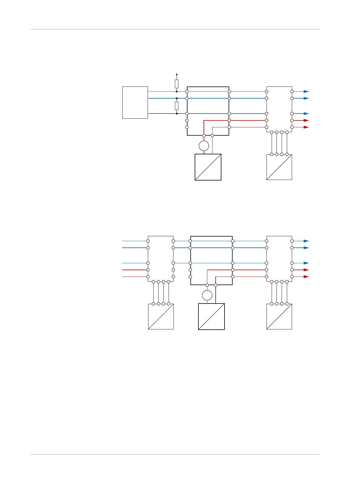
3.4.4.2 Auxiliary energy supply
The following illustrations explain the principle of the power supply of the FT90
in the Modbus network. However the feeder nodes are not part of the delivery
scope and need to be installed by the operator.
BUS-D1
BUS-D0
BUS-R
AC/DC
AC
BUS-D1
BUS-D0
BUS-R
U
b
+
U
b
-
1
3
2
4
5
FT90
Master
+
Auxiliary energy
Feed
1
3
2
4
5
1
3
2
4
5
ST1 ST2
1
3
2
4
5
A
max. 2A
(~)
(~)
T/rH
ST3
1 2 3 4
1 2 3 4
Temperature and humidity sensor
FF90
U+
SCL
GND
SDA
Fig.25: Main supply
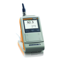
Please note that the M12 connectors are approved for max. 2A. This value can
be exceeded with more than just 12 devices of the type FT90. In this case, an
intermediate auxiliary energy feed should be provided at a suitable place.
AC/DC
AC
BUS-D1
BUS-D0
BUS-R
U
b2
+
U
b2
-
1
3
2
4
5
FT90
Auxiliary energy 2
Feed
1
3
2
4
5
1
3
2
4
5
ST1 ST2
FT90
1
3
2
4
5
1
3
2
4
5
ST1 ST2
BUS-D1
BUS-D0
BUS-R
2
4
5
1
3
A
max. 2A
(~)
(~)
U
b
+
U
b
-
(~)
(~)
T/rH
ST3
1 2 3 4
1 2 3 4
Temperature and
humidity sensor
FF90
U+
SCL
GND
SDA
T/rH
ST3
1 2 3 4
1 2 3 4
Temperature and
humidity sensor
FF90
U+
SCL
GND
SDA
Fig.26: Intermediate supply