5 | Operation FISCHER Mess- und Regeltechnik GmbH
64/108 BA_EN_FT90
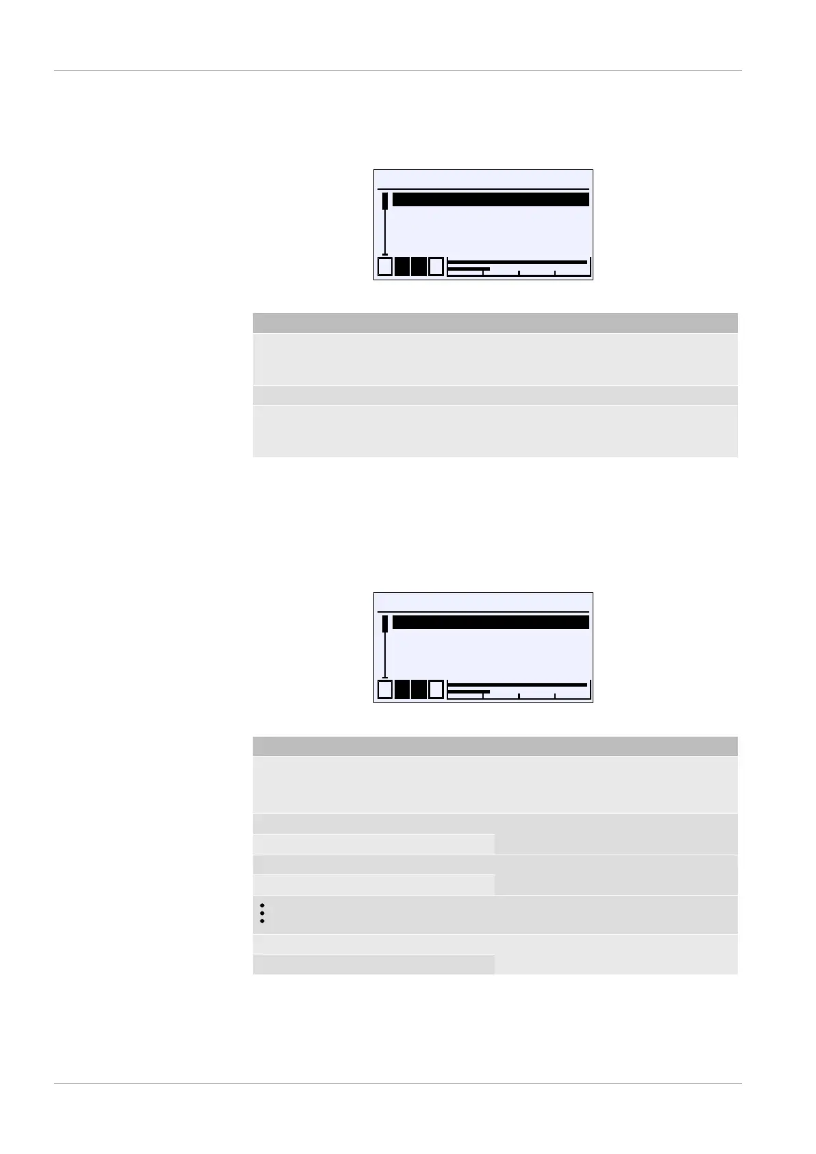
5.5.1.3.2 Characteristic C1 (Table)
Path: \Configuration\Channel 1\Characteristic C1
Level: 3
\...\...\Characteristic C1
1 2 3 4
Displ.range C1 unit
Table C1
Back
U
E
A
Fig.89: Characteristic C1 (table)
Menu name Description
Displ.range C1 unit A unit for the display value is defined
with this parameter. It must have a
length of at least 5 characters.
Table C1 A The table is defined in this menu.
Back E This represents the output (exit) of the
menu. It is used to return to the Chan-
nel 1 menu.
The table function can be used to correct the input characteristic of the sensor
at any point. The changes impact on the display value and the output signal.
5.5.1.3.2.1 Table C1
Path: \Configuration\Channel 1\Characteristic C1\Table C1
Level: 4
\...\...\...\Table C1
1 2 3 4
Disp. Value pairs
Input value 1
Display value 1
U
Input value 2
Fig.90: Table C1
Menu name Description
No. Value pairs This parameter is used to define the
number of value pairs.
Value range: ... 2 ... 30
Input value 1 Value pair 1
Display value 1
Input value 2 Value pair 2
Display value 2
Input value 30 Value pair 30
Display value 30
Each support point is stated by a value pair comprising the Input value x
and Display value x . The index x states the number of the value pair. At
least two value pairs always need to be stated. The maximum number of value
pairs is 30.