5 | Operation FISCHER Mess- und Regeltechnik GmbH
68/108 BA_EN_FT90
5.5.1.3.3.2 Formula C1
Path: \Configuration\Channel 1\Characteristic C1\Formula C1
Level: 4
\...\...\...\Formula C1
1 2 3 4
Standard
Comefri
EBM Papst
Fläkt Woods
S
R
U
R
R
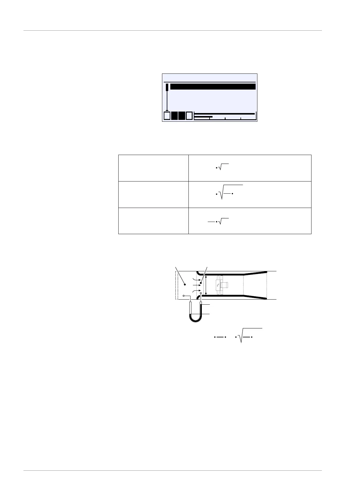
Fig.95: Formula C1
The following table lists the formulas specified by the respective manufacturer
for calculating the volume flow.
Comefri
EBM Pabst
Fläkt Woods
Nicotra Gebhardt
Rosenberg
Ziel-Abegg
q = k
2
ρ
q = k Δp
q =
k
Δp
1
Δp
Standard
Fig.96: Volumetric flow measurement Manufacturer's formulas
Volume flow measurement at the inlet cone
q:
k:
volume flow
calibration factor
Δp: differential pressure
ρ: density
D
Δp
inlet cone
q = c
2
ρ
Δp
π
4
D
2
c: flow coefficient
basic formula
suction chamber
D: diameter
Fig.97: Volume flow measurement
Fans are usually equipped with an inlet cone. The volume flow measurement
consists of one or more measuring points in the inlet cone and one measuring
point in the suction chamber of the ventilation unit. The differential pressure
between the measuring points is used to calculate the volume flow.
The basic formula given applies to a frictionless and loss-free flow with constant
density. In reality, therefore, a correction value caused by the design and other
factors must be taken into account.
The fan manufacturers have determined the correction value for each inlet
nozzle. In general, these values are called calibration factor or K-factor and can
be found in the data sheet or operating instructions of the volume flow measur-
ing device.