DAD 143.x User Manual Profinet Rev.1.1.1 March 2023 Page 52 of 95
9.8 Logic Input Functions & Status
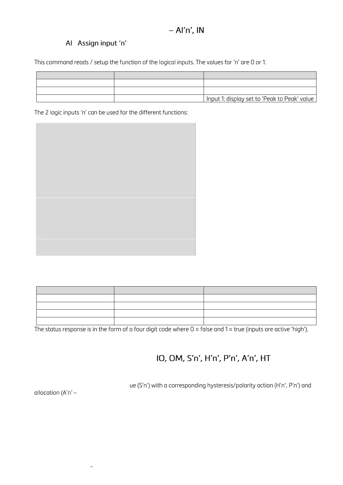
9.8.1
[Index 0x2D00 Sub 0x01 / 0x02]
Slave (DAD143.x) responds
Reading Input 1: no function
00 - Input "n" has no function
01 - Input "n" acts as Zero button
02 - Input "n" acts as Tare button
03 - Input "n" acts as Up arrow button
04 - Input "n" acts as Down arrow button
05 - Input "n" starts the Trigger function
06 - Input "n" displays the Average value
07 - Input "n" displays the Peak value (maximum)
08 - Input "n" deletes the Peak value (maximum)
09 - Input "n" displays the Hold value
10 - Input "n" displays the Peak to Peak value
11 - Input "n" displays the Valley value (minimum)
12 - Input "n" disables the buttons
13 - Input "n" stores the actual weight (Hold value)
14 - Input "n" tares the displays and deletes all other values
15 - Input "n" turn off display
9.8.2 IN Read status of the logic inputs
[Index 0x2100 Sub 0x07]
This command reads the status of the digital inputs.
Slave (DAD143.x) responds
Reading: Input 0 or 1 inactive
Reading: Input 0 and 1 active
The least significant bit corresponding to Input 0.
9.9 Logic Output Commands -
The definitions for this section may be changed due to the fact that the definitions of the logic outputs for the
DAD143.x, where the status depends on the weight value (setpoint) are to be defined. Each logic output can be
assigned an independent setpoint val
switch on the gross, net, peak, average etc. weight).
9.9.1 IO Read / Modify the Status of the logic Outputs
[Index 0x2100 Sub 0x06]
This command reads and can modify the status of the logic outputs (if enabled by the OM command). The
status response is in the form of a four digit code where 0 = false and 1 = true (outputs are normally open,
open drain MOSFETs), the least significant bit corresponding to Output 0 etc.

 Loading...