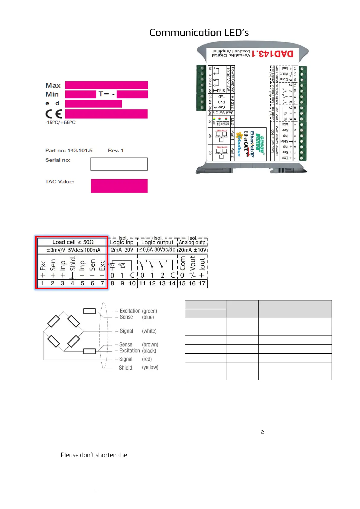
3.2 Terminals Load Cell Connection
Colour code of e.g. standard load cells
3.3 Load Cell Connection
The load cell wiring should be made carefully before energizing to avoid damages to the amplifier and the
load cells. The input resistance of the load cells that you want to connect should be 50 Ω (ohms).
In case of using a load cell / scale with 4 wire cable, you have to short-circuit (bridge) the pins 1 & 2 and 6 & 7.
Remark:
4-wire cable of a load cell, as the cable is part of the factory calibration for
signal & temperature compensation.

 Loading...