DAD 143.x User Manual Profinet Rev.1.1.1 March 2023 Page 12 of 95
3.9 Logic Inputs & Outputs
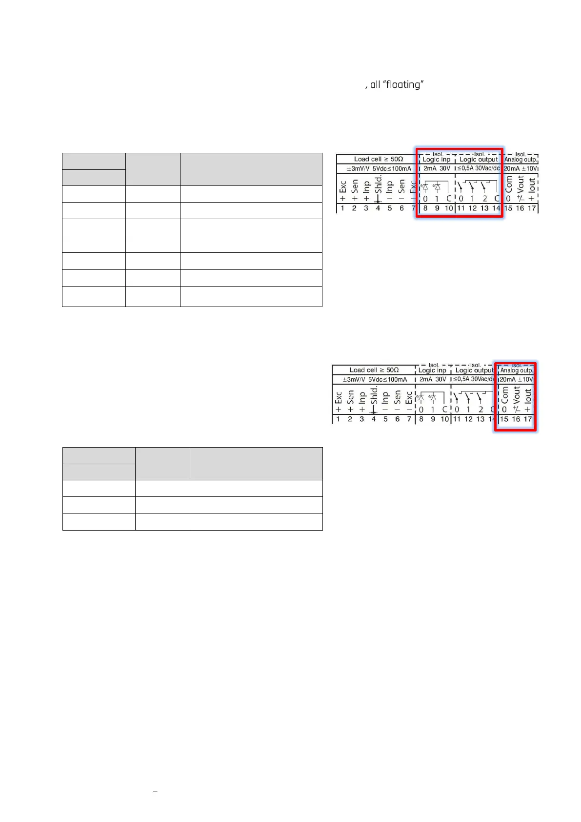
The DAD143.x offers 2 isolated logic inputs and 3 isolated logic outputs .
The 2 inputs can e.g. get the function to act as the ZERO or TARE button, see chapter 9.8.1.
The 3 outputs act as switches for setpoints with hysteresis, switch behavior etc. Several reference values such
as net weight, peak weight or average can be used, see chapter 9.9.3.
3.10 Analog Outputs
The DAD143.x offers 2 isolated analog outputs for current
and voltage. For your application you can choose one of the
six modes like:
➢ 4 to 20mA / 0 to 20mA
➢ 0 to +5V / 0 to +10V
➢ -5 to +5V / -10 to +10V.
Remark:
The DAD143.2 has no analog outputs.
Note Logic Inputs:
The pulse duration must be at least 50ms.
Note Logic Outputs:
The connection C can be used for either
‘high’ level (24V AC/ DC) or ‘low’ level (0V).
 Loading...
