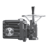
Limitorque QX Electronic Actuator FCD LMENIM3306-06 – 07/14
10
2.1 Calibrate Position Limits
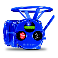
1. Confirm that the QX actuator is correctly installed on the valve as described in Section 3 Installation and Operation.
2. Refer to the nameplate for the correct main power supply voltage. Switch on the main power to the unit.
3. Turn the red knob to the “STOP” position. The “SET UP ENGLISH?” message will be displayed, select “YES”. The
“SET CLOSE POSITION LIMIT?” message will then be displayed. Proceed with setting the open and close limits of
the valve.
4. Calibrate end position limits one of two ways:
• Electrically, using the control panel. See Section 2.1.1, Electrical Operation Feature.
• Manually, using the handwheel. See Section 2.1.2, Handwheel Operation Feature.
Once the position limits have been set, the LCD message will indicate the valve position as a percentage of the valve
opening.
While setting limit switches, place the red selector knob in the “LOCAL” position to permit the actuator to run open or
closed in push-to-run mode (inching) only.
a
CAUTION: Extreme care must be taken as the valve approaches its end position.
The unit will not function with the red selector knob in the “REMOTE” position until both limit switches are set.
The existing configuration of the actuator/valve parameters may be viewed by entering the “SETUP” mode.
2.1.1 Electrical Operation Feature
This feature allows for quick and simple calibration. From a virgin startup, the “SET CLOSE POSITION LIMIT?” message
will be displayed once the setup language has been selected.
NOTE: Refer to Figure 2.1 – Electrical operation as a guide during setup
a
CAUTION: Do not adjust close stop while stop is loaded. It is highly recommended that the stops be turned until
they are almost removed from the housing before setting the limits. Once the limits have been set, then the
stops maybe tightened. Refer to Figure 2.3.
Closed Position Limit
1. “SET CLOSE POSITION LIMIT?” is displayed on the LCD.
2. Select “YES.” The “CLOSE VALVE - OK?” message is displayed.
3. Switch the actuator to “LOCAL” control and use the open/close switch to position the valve to the desired closed
position.
4. Back out the close stop if needed. First loosen the screw securing the stop then move stop.
NOTE: Do not adjust close stop while stop is loaded.
5. When the valve is in the desired position, switch the actuator back to “STOP” and select “YES” again. The LCD will
read “SAVE CLOSE LIMIT OK?”
6. Select “YES” if the valve’s close limit position is correct. The close position limit is set.
7. Turn the close stop against the drive sleeve, then back off the close stop from the drive sleeve approximately 0.5 to
1.5 turns, ensuring the stop does not contact the drive sleeve.
 Loading...

