7
Limitorque QX Electronic Actuator FCD LMENIM3306-06 – 07/14
flowserve.com
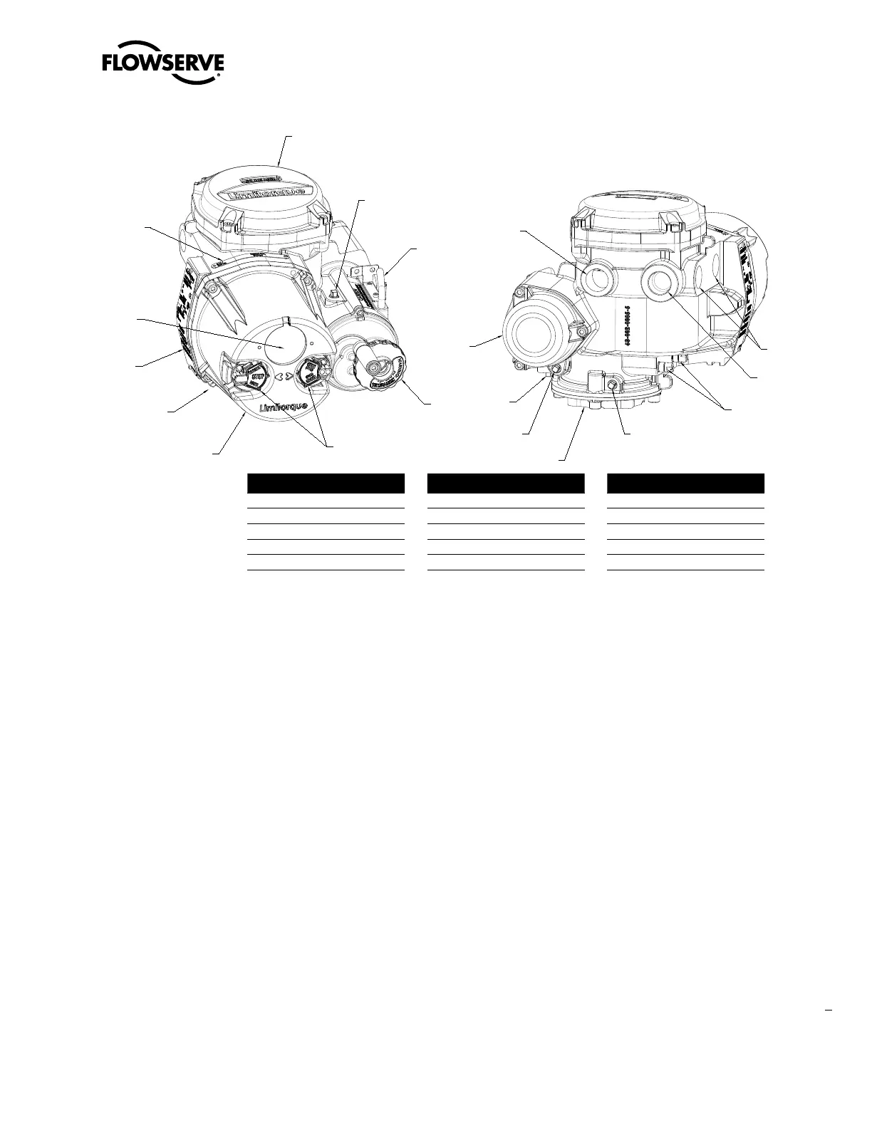
Figure 1.1 – QX-05 Actuator
13
12
3
1
4
6
10
2
7
5
11
3
3
14
9
9
9
OPTIONAL
8
15
1
Important Notes
• Please read this manual in its entirety before attempting to install or operate your QX actuator. A full understanding
of the installation and operation options will assist you in installing the actuator in the most effective manner.
Limitorque has designed the QX actuator for long life even in the harshest environments. Flexible control and protec-
tion options are provided to ensure the actuator meets your requirements.
• All actuator enclosures are sealed by O-rings, and cable entries are supplied with threaded plugs to protect the
terminal compartment until the unit is wired. If the actuator cannot be installed immediately, it is recommended that
it be stored in a clean, dry place, preferably in an area that is not subject to large fluctuations in temperature.
• Disconnect all incoming power before opening any cover on the actuator. The user/operator must ensure that safe
working practices are employed at all times and are in accordance with local or national standards that are enforced
at the particular site.
• To install and commission the actuator, only the terminal compartment cover needs to be removed. See Figure
1.1, Item 10. Settings for commissioning the actuator are done externally; therefore, no other covers need to be
removed. The actuator was assembled in ideal dry conditions and the total sealing of the enclosure protects all
electrical components against deterioration.
Piece Description
1 Handwheel
2 Declutch Lever (QX-05)
3 Oil Fill
4 Controls Cover
5 LCD
Piece Description
6 Control Knob
7 Ground Lug
8 Baseplate
9 Conduit Entry
10 Terminal Compartment
Piece Description
11 Motor
12 Certification Nameplate
13 Tag Nameplate
14 Oil Plug
15 Stem Nut Stops