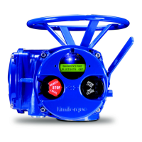
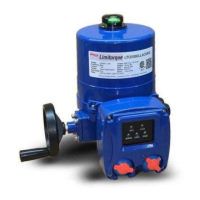
Limitorque QX Electronic Actuator FCD LMENIM3306-06 – 07/14
18
3.2 Mechanical Installation onto Valve or Gearbox
Before installing the actuator onto a valve or gearbox, check the following to ease installation:
• Verify that mounting flange is suited dimensionally to mate with the actuator base. Ensure that it is perpendicular to
the valve stem.
• Ensure the stem nut mates with the valve stem or input shaft. Keyed or splined shafts should exhibit a smooth,
sliding fit with the key installed.
• Ensure there is adequate engagement of the stem nut with the valve stem or input shaft when mounted. Generally, the
minimum length of engagement is 1.5 times the diameter of the stem.
• Ensure that the valve stem is not too long such that it bottoms out on the QX drive sleeve.
• Verify that mounting studs or bolts are the correct length to suit the thickness of the mounting plate.
• Verify hardware specifications for English style:
• Socket head cap screw per ASTM A 574 and ANSI 18.3.
• Hex head cap screw per SAE J429 Grade 5.
• Verify hardware specifications for metric style: hex and socket head cap screws per Property Class 12.9.
• Clean and lubricate the valve stem or input shaft.
• Ensure adequate lifting facilities and slings are available at the installation site.
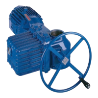
NOTE: Do not use the handwheel to lift the actuator.
3.3 Electrical Connections
Verify that the supply voltage details on the nameplate are correct for this installation. Setup is non-intrusive; therefore,
remove only the terminal cover to make electrical connections and to commission the actuator.
c
WARNING: The removal of any other covers without Limitorque’s approval will void the warranty. Limitorque
will not accept responsibility for any damage or deterioration that may occur as a result of cover removal.
3.3.1 Removing Terminal Cover
Remove the terminal cover as follows:
1. Remove the four cover screws using a 6 mm hexagonal wrench.
2. Remove the cover. XP units have long-spigoted covers and two tapped holes 180° apart. If the XP cover is difficult
to remove, fit two of the cover screws into the tapped holes in the cover flange and jack out the cover. Take care to
turn the screws by equal increments. Do not lever the cover off with a screwdriver, or similar object, since this may
damage the flamepath on an explosionproof unit or the O-ring seal and seating face.
3.3.2 Terminal Compartment Documents
The OEM and user installation kits, wiring diagram, and test report are contained in the terminal compartment or with
the actuator. Do not place them in the terminal compartment when the electrical connections have been completed.
NOTE: This instruction does not apply to valve manufacturers or similar installers of the actuator onto a valve prior to
shipping to site. It is important that these items are available at the final destination site.

 Loading...

