17
Limitorque QX Electronic Actuator FCD LMENIM3306-06 – 07/14
flowserve.com
Disassembly – Flange 2
1. Remove the two torque nut mounting screws and remove the torque nut.
2. Machine the torque nut to suit the valve stem or gearbox input shaft. Ensure sufficient clearance for a smooth,
sliding fit.
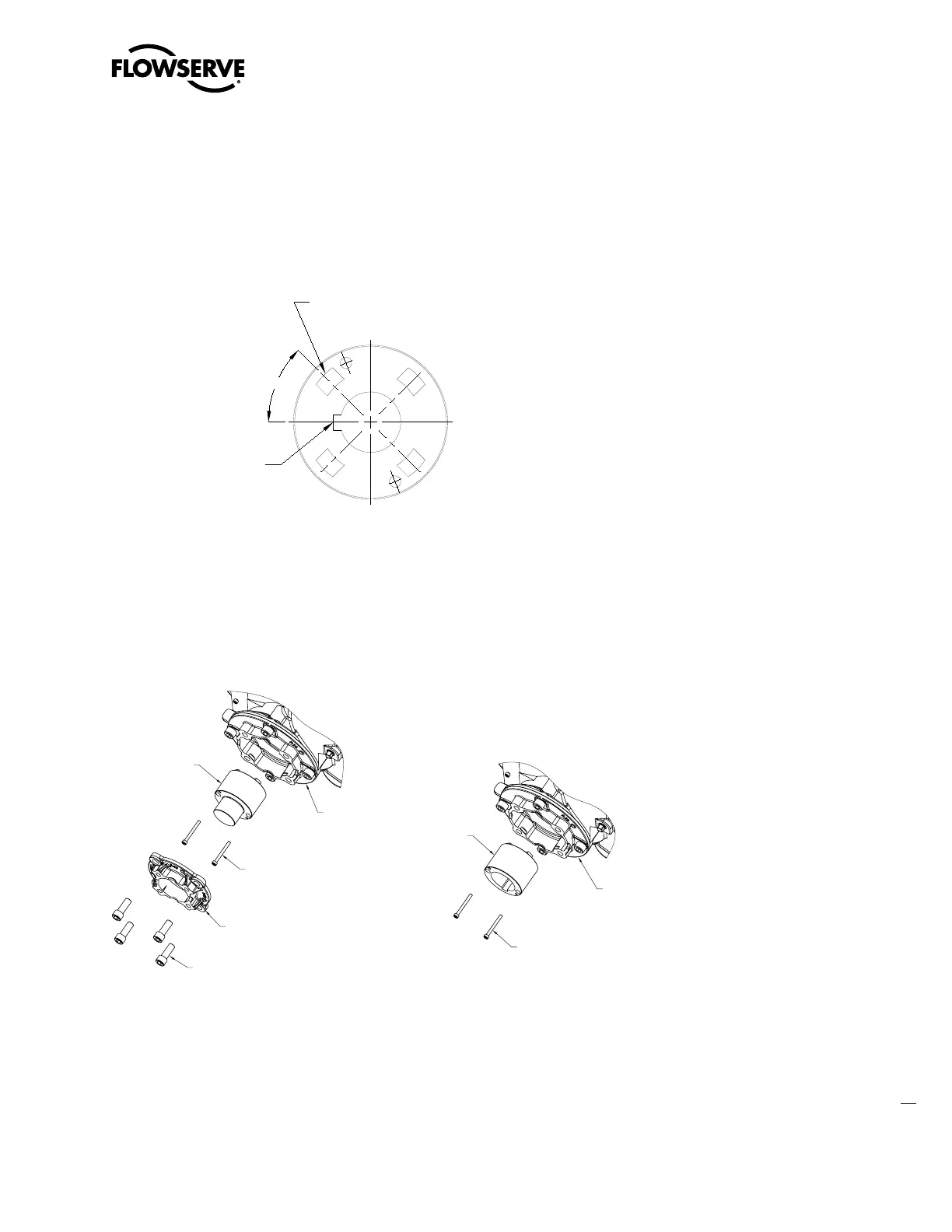
Figure 3.1 - Top view - Stem nut with standard keyway position
Reassembly
1. Clean the torque nut thoroughly and lightly grease.
2. Replace the torque nut in the drive sleeve. Ensure the torque nut meshes with the drive lugs.
3. Reinstall the torque nut mounting screws.
Figure 3.2 – Exploded view of QX bases
45°
TOP VIEW - STEM NUT
W/ STD KEYWAY POS.
DRIVE SLEEVE LUGS
STRADDLE
C
L
STANDARD KEYWAY
POSITION 45
°
OFF LUGS
(SEE NOTE 1)
STAND
BASEPLAT
TORQUE NUT
TORQUE NUT
MOUNTING SCREWS
STANDARD
BASE PLATE
TORQUE NUT
TORQUE NUT
MOUNTING SCREWS
SMALL BASE PLATE
SMALL BASE PLATE
MOUNTING SCREWS
QX-1 F/FA05 & F/FA07, QX-2 F/FA07 Base,
QX-3 F/FA10 Base
QX-1, -2 F/FA10 Base
QX-3, -4, -5 F/FA12 & 14 Base