Limitorque QX Electronic Actuator FCD LMENIM3306-06 – 07/14
74
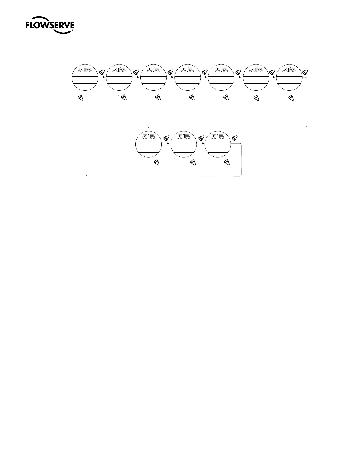
Figure 4.32 – Monitor relay
YES YES YES
YES YES YES
YES YES YES YE
NO
NO NO NO
NONO
NO
NO
NONO
CHANGE
MONITOR RELAY?
SELECT
SETTINGS?
L0CAL
ENABLED-OK?
ENABLED-OK? ENABLED-OK? ENABLED-OK?DISABLED-OK?DISABLED-OK?
DISABLED-OK? DISABLED-OK?DISABLED-OK?
LOCAL STOP
ENABLED-OK?
INHIBIT SIGNAL
DISABLED-OK
ESD SIGNAL
DISABLED-OK?
PS ENABLE ACTIVE
ENABLED-OK?
PS ENABLE FAULT
ENABLED-OK?
ESD RELEASE FAULT
ENABLED-OK?
OVERTORQUE
DISABLED-OK?
The three following options will only show if the
customer has purchased and enaled custom option 1.
These functions are monitored continuously and may not be changed, but an additional three functions may be
configured individually during setup.
1. Select “CHANGE MONITOR RELAY?” from the “SETUP” routine.
2. Select “YES” to enter the “SELECT SETTINGS?” display. Select “YES” to access each of the following three
functions:
• “OVERTORQUE” – Torque range exceeded in mid-travel, thermistor temperature exceeded, or malfunction in
thermistor
• “INHIBIT SIGNAL” – Inhibit “ON” and active
• “ESD SIGNAL” – ESD “ON” and active
3. Select “NO” to:
• “ENABLED” – will trip monitor relay
• “DISABLED” – will not trip monitor relay
4.22 Diagnostic Reset
For diagnostic purposes the following parameters are recorded at certain points in the valve travel on every opening and
closing stroke:
• Proportional measurements of torque
• Drive sleeve turns
• Contactor operations
• Maximum and minimum voltage
• Motor run time
• Stroke time
To enable the new values to be compared with previous measurements, it is essential to record reference values.
Limitorque recommends this be done after the valve has been installed, commissioned, and is operating under normal