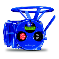
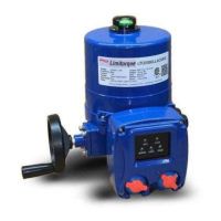
Limitorque QX Electronic Actuator FCD LMENIM3306-06 – 07/14
16
3
Installation and Operation
3.1 Preparing the Stem Nut
The QX has two (2) basic base designs:
• Torque-only (90º) operation
• Multi-turn operation (up to 20 multi-turn rotations - 7200º total)
3.1.1 Torque Applications
Standard B4/B4E Base
The standard QX actuator base is the stem nut for torque-only. It includes a mounting plate and steel torque nut, which
may be machined to fit a valve or gearbox. A B4E torque nut can be provided and may be installed to allow for extended
stem acceptance.
Table 3.1 – Available QX Flanges
QX-1 QX-2 QX-3 QX-4 QX-5
Flange 1
ISO 5210 F05/F07 F07 F10 N/A N/A
MSS SP-102 FA05/07 FA07 FA10 N/A N/A
Flange 2
ISO 5210 F10 F10 F12 (OPT)
F14 (STD)
F12 (OPT)
F14 (STD)
F14
MSS SP-102 FA10 (STD) FA10 (STD) FA12 (OPT)
FA14 (STD)
FA12 (OPT)
FA14 (STD)
FA14 (STD)
Disassembly – Flange 1
1. Remove base plate mounting screws and small base plate.
2. Remove the two torque nut mounting screws and remove the torque nut.
3. Machine the torque nut to suit the valve stem or gearbox input shaft. Ensure sufficient clearance for a smooth,
sliding fit.
 Loading...

