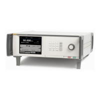
Pressure Controller/Calibrator
Return to Service – Safety Validation Recommendations
75
Return to Service – Safety Validation Recommendations
The following sections of this manual focus on the disassembly, rebuild, and
upgrade of the Product for mechanical, electrical, and firmware. To verify safe
operation of the Product after maintenance or repair, read the following sections.
Electrical
If service work is done to the ac power entry, ac power wiring, ac/dc supply,
grounding, or components in the near vicinity, then Fluke Calibration
recommends Hypot and Ground Bond testing per IEC 61010-1 Annex F.
Pressure
If Service work is done to any pressure boundary parts or sealing surfaces, then
Fluke Calibration recommends that basic pressure performance (control several
pressure points) and leak testing (refer to Leak Test) are done for 60 seconds to
the highest pressure rating for the given chassis or module installation. Do this
test after the system is completely assembled with the top cover installed.
For all service work, a basic functional test of the system must be done prior to
the Product’s return to service. These recommendations are for a basic
configuration of chassis with PCM and PMM:
1. Power Cycle – confirm that the system boots properly and recognizes the
modules.
2. Touch Screen test – confirm that the touch screen works by touching Setup.
The display should show the Setup screen. Push Exit to return to the main
screen.
3. Keypad test – Confirm the keypad works by changing an entry field. Select
the setpoint field and enter a number, push
, enter a zero, push . The
field should change per the entered values.
4. Verify Modules are recognized:
a. SETUP>Diagnostic>Control>Primary – Shows details of the
installed PCM.
b. SETUP>Diagnostic>Measure – Shows details of the installed PMMs
and related module pressure, temperature, and isolation valve states.
5. Front Door Function – Unlatch and open the door of the chassis. The system
recognizes the open-door condition and initiates the venting sequence. Close
the front door to return the system to an operational state.
6. Refer to the above sections regarding Electrical and Pressure testing.
If any of these tests fail, then the failure needs to be resolved immediately. Refer
to the appropriate sections of this manual and review the prior service work.

 Loading...