FRICK QUANTUM CONTROL PANEL
OPERATION
S90-010 O
Page 24
Low Motor Amps Shutdown Delay - The minimum
time in seconds that the Motor Amps is less than or
equal to the low Motor Amps shutdown setpoint before
the compressor will shut down.
Forced Unload Load Inhibit Delay - (If applicable, refer-
ence Appendix C). Once a Force Unload condition is
cleared, this is the amount of time in seconds that the
compressor is inhibited from loading.
The following special selections are on this screen:
Clear Remaining Delay - This selection will cause a
message box to appear saying “WARNING!!! This may
cause damage to the motor. Continue?”. Select the [OK]
key to clear the Recycle Delay time or select the [Can-
cel] key to void clearing this timer.
Power Fail Restart - This selection is available if this
option was enabled in Panel Setup. This selection
displays the “Power Failure Restart” screen. This screen
has the following setpoints:
Time after power fail allowing restart - The num-
ber of hours and minutes that the compressor is
allowed to restart in its previous mode after a power
loss can be changed.
DBS Motor Starter - This selection is available if this
feature was selected in Factory Setup. This selection
displays the “RAM DBS Motor Starter” screen.
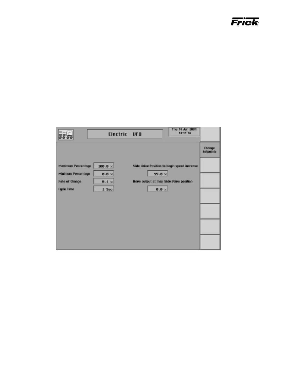
CONTROL SETUP - MOTOR CONTROL SETPOINTS - “Electric – VFD” SCREEN
Hardware Signals
4 – 20 ma analog output - Signal from the Quantum to
provide the speed setpoint to the VFD controller. The VFD’s
controller and hardware will need to be configured to the
minimum and maximum desired speed. The minimum
speed will vary depending on compressor type, consult the
factory for application assistance.
4 – 20 ma analog input - Analog input channel on the
Quantum to monitor the actual RPM’s of the drive. This sig-
nal is for monitoring purposes only.
Setpoints related to the VFD speed control output.
Maximum output - Setpoint used to select the maximum
operating speed of the VFD. Selectable from 1-100% of the
Quantum’s 4-20ma signal.
Minimum output - Setpoint used to select the minimum
operating speed of the VFD. Selectable from 1-100% of the
Quantum’s 4-20ma signal.
Rate of change - Setpoint used to adjust the speed changes
sent to the VFD based on the capacity control Selectable
from .1-25% of the 4-20ma signal.
Cycle Time - Setpoint used in conjunction with the “Rate of
change” setpoint to adjust the time between speed changes
sent to the VFD. Selectable from 1-30 seconds.
Slide Valve Position to begin Speed Increase - The Slide
Valve position which must be obtained before the VFD will
begin increasing speed. Selectable from 0-100% of the
compressors Slide Valve position. This setpoint is used in
conjunction with the “Drive Output at Max SV position”.
Drive Output at Max SV position - The desired speed of
the VFD when the compressors Slide Valve position reaches
100%. This setpoint is selectable from 1-100% of the
Quantum’s 4-20ma signal and is used in conjunction with
the “Slide Valve Position to begin Speed Increase”.
NOTE: See “Electric, VFD, Engine, Turbine” flowchart for
further information.