FRICK QUANTUM CONTROL PANEL
OPERATION
S90-010 O
Page 25
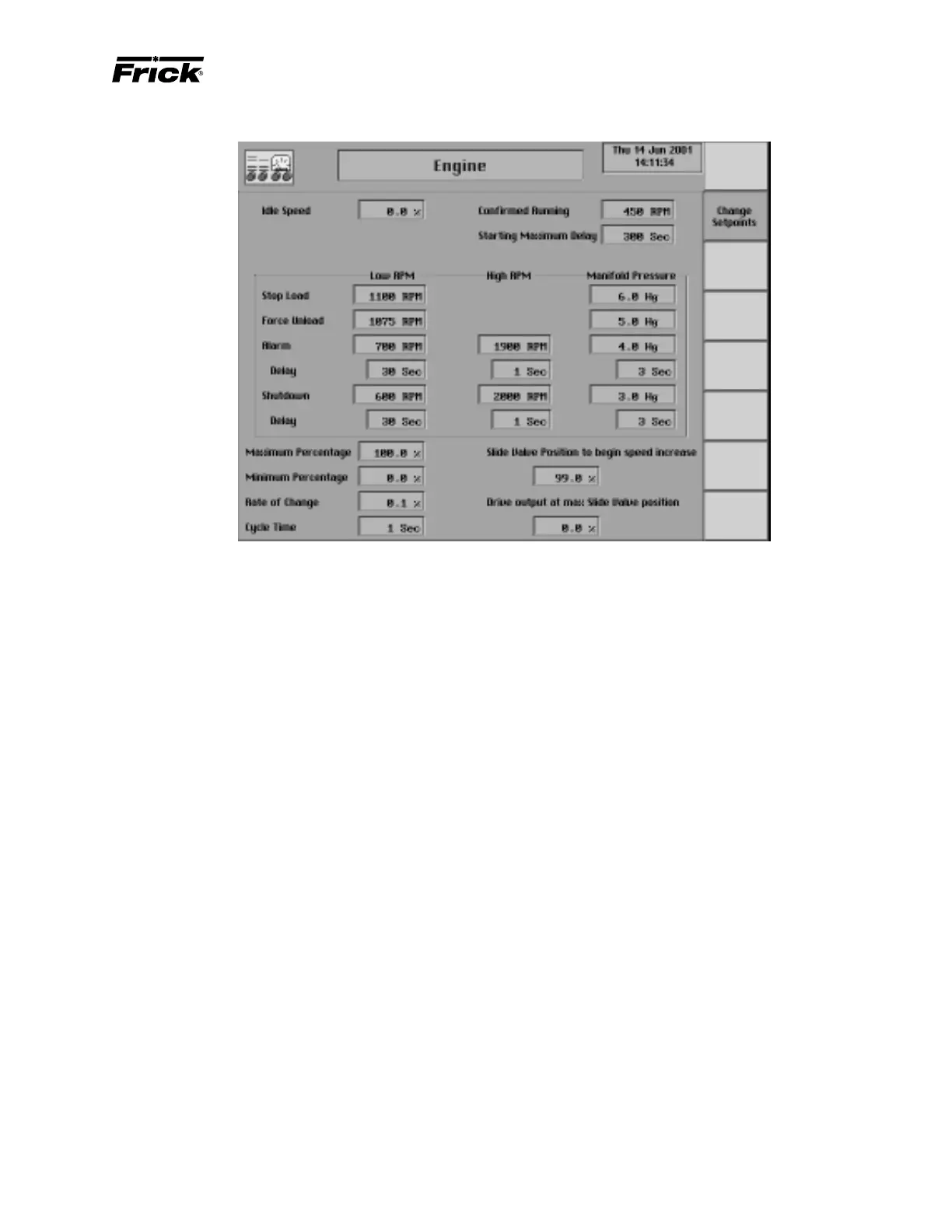
CONTROL SETUP - MOTOR CONTROL SETPOINTS - “Engine”
Hardware Signals
4 – 20 ma analog output - Signal from the Quantum to
provide the speed setpoint to the speed governing device.
The speed governing device’s controller (i.e. Electronic Gov-
ernor) and hardware will need to be configured to the mini-
mum and maximum desired speed. The minimum speed
will vary depending on compressor type, consult the factory
application assistance.
4 – 20 ma analog input - Analog input channel on the
Quantum to monitor the actual RPM’s of the drive. This sig-
nal can be sent to the Quantum from the speed governing
device if available or generated from a magnetic pickup
located on the flywheel teeth wired to a frequency to 4-20
ma converter.
Manifold Pressure (Engine only) - Pressure signal required
from the engine to detect and respond to overload
conditions.
Setpoints related to the Engine speed control output.
Maximum output - Setpoint used to select the maximum
operating speed. Selectable from 1-100% of the Quantum’s
4-20ma signal.
Minimum output - Setpoint used to select the minimum
operating speed. Selectable from 1-100% of the Quantum’s
4-20ma signal.
Rate of change - Setpoint used to adjust the speed changes
sent to the VFD based on the capacity control requirements.
Selectable from .1-25% of the 4-20ma signal.
Cycle Time - Setpoint used in conjunction with the “Rate of
change” setpoint to adjust the time between speed changes
sent to the VFD. Selectable from 1-30 seconds.
Slide Valve Position to begin Speed Increase - The Slide
Valve position which must be obtained before the speed
will begin to increase. Selectable from 0-100% of the com-
pressors Slide Valve position. This setpoint is used in con-
junction with the “Drive Output at Max SV position”.
Drive Output at Max SV position - The desired speed of
the engine/turbine when the Slide Valve position reaches
100%. This setpoint is selectable from 1-100% of the
Quantum’s 4-20ma signal and is used in conjunction with
the “Slide Valve Position to begin Speed Increase”.
High RPM Alarm - If the RPM is greater than or equal to this
setpoint, for the alarm time delay, an alarm occurs.
High RPM Shutdown - If the RPM is greater than or equal to
this setpoint, for the shutdown time delay, the compressor
will shut down.
High RPM Alarm Delay - The minimum time in seconds
that the RPM is greater than or equal to the High RPM
alarm setpoint before notification of the alarm.
High RPM Shutdown Delay - The minimum time in sec-
onds that the RPM is greater than or equal to the High RPM
shutdown setpoint before the compressor will shut down.
Low RPM Stop Load - If the RPM is less than or equal to this
setpoint, the compressor will be prevented from further load-
ing until the RPM is greater than this setpoint. This setpoint
helps avoid forced unloading.
Low RPM Force Unload - If the RPM is less than or equal to
this setpoint, the compressor will be forced to unload until
the RPM is greater than this setpoint. This setpoint helps
avoid a low RPM alarm or shutdown.
Low RPM Alarm - If the RPM is less than or equal to this
setpoint, for the alarm time delay, an alarm occurs.