FRICK QUANTUM CONTROL PANEL
OPERATION
S90-010 O
Page 32
POINTS” SCREEN
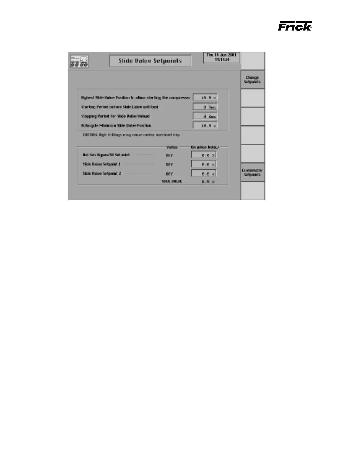
The “Slide Valve Setpoints” screen is shown if it applies to
this compressor model (Reference “Compressor Model Dif-
ferences”). The following Slide Valve setpoints are on this
control setpoint screen:
Highest Slide Valve Position to allow Compressor
Start - If the Slide Valve is above this Slide Valve posi-
tion the compressor will not be allowed to start.
Starting Period before Slide Valve will load – The
amount of time, in seconds, after the compressor starts,
that the Slide Valve will not load. This timeout period is
displayed on the Operator Status screen as a “Stop
Load Starting Inhibit” message with time to expire.
Stopping Period Slide Valve Unload – This setpoint
comes in to play if the value is > zero and the [Com-
pressor Manual Stop] button is pressed. The com-
pressor will not stop, but will enter a stopping mode in
which the Slide Valve is given a Force Unload until it is
below the “Highest Slide Valve Position To Allow Start-
ing The Compressor” setpoint before stopping –OR–
the timeout period expires.
Minimum Slide Valve Position when in Autocycle - If
automatic cycling (autocycle) is active, this is the slide
valve position a running compressor will not unload
below. This setpoint is useful for pumping down the
refrigerant in a system.
Note the warning that says: “CAUTION: High settings
may cause motor overload trip.”
Note: During the compressor stopping, the Slide Valve
unload solenoid remains energized until the Slide Valve
is unloaded to or below the “Highest slide valve position
to allow starting the compressor” setpoint. If the Slide
Valve does not unload below this setpoint within 5 min-
utes, the alarm message “Compressor Unable to Un-
load - Alarm” is issued.
The Hot Gas Bypass and Slide Valve Setpoints digital out-
puts are displayed on the Slide Valve setpoints display if it
applies to this compressor model (Reference “Compressor
Model Differences”) and if “Hot Gas Bypas/SV Setpoint”
was enabled in Panel Setup. The on or off status of the
outputs and the setpoint will be shown. The following out-
puts are used as an indicator of a Slide Valve position:
Hot Gas Bypass/Slide Valve Setpoint - This output is
intended to be used for either Hot Gas Bypass control
or as an indication of a Slide Valve position.
Slide Valve Setpoint 1
Slide Valve Setpoint 2
The following setpoint for the digital output is provided:
On when below - The digital output is turned on when
the Slide Valve position is below this setpoint and turned
off when the Slide Valve position equals or exceeds
this setpoint.
The following special selection is on this display:
[Economizer Setpoints] - The following Slide Valve
position setpoints are on this display:
On when above - The Economizer digital output
(module 11on digital board #1) is turned on when
the Slide Valve position is greater than this setpoint.
Off when below - The Economizer digital output
(module 11on digital board #1) is turned off when
the Slide Valve position goes below this setpoint.
Note: These setpoints are active only when the com-
pressor is running.