79
EN-US
(7) Field for entering a minimum time for which the output I/O 1 is to be activated for
each switch-on process
(8) Field for activating the maximum runtime per day
(9) Field for entering a maximum time for which the output I/O 1 is to be activated in
total per day (several switch-on processes are included).
Target runtime
(10) Field for activating a target runtime
(11) Field for entering a minimum time for which the output I/O 1 is to be activated in
total per day (several switch-on processes are included)
(12) Field for selecting the hour, if the target runtime is to be achieved by a certain time
(13) Field for selecting the minute, if the target runtime is to be achieved by a certain
time
(14) "Apply/Save" button
(15) "Cancel/Discard entries" button
(16) Status display
If the mouse pointer is moved over the status, the reason for the current status is
displayed.
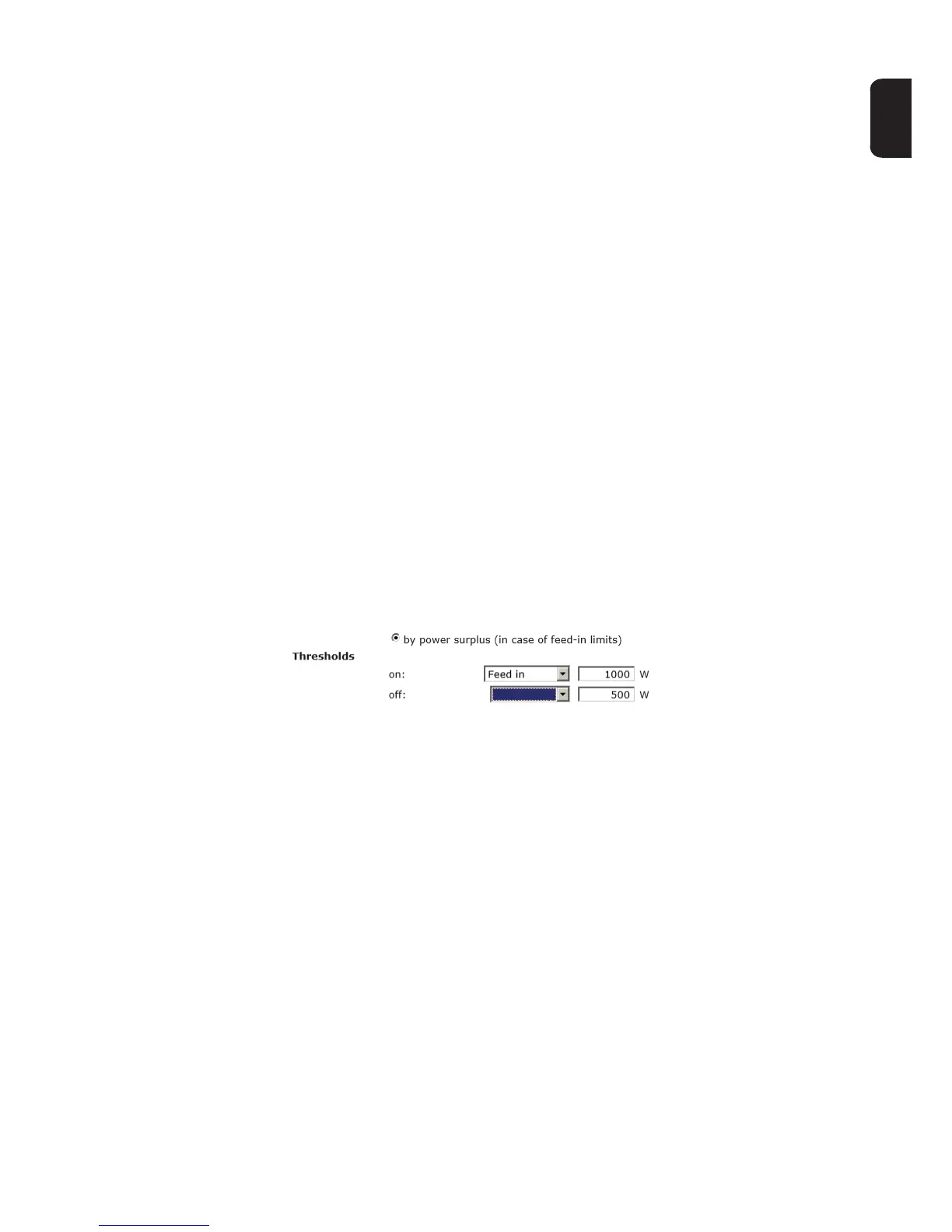
If "by excess power" is selected under "Control", additional selection fields for Feed (3a)
and Reference (3b) are displayed under "Thresholds":
(3)
(4)
(5)
(3a)
(3b)
Consumption