91
EN-US
The ripple control signal receiver and the Fronius Datamanager 2.0 plug are connected to
one another using a 4-pin cable in accordance with the connection diagram.
For distances of greater than 10 m between Fronius Datamanager 2.0 and the ripple con-
trol signal receiver, a shielded cable is recommended.
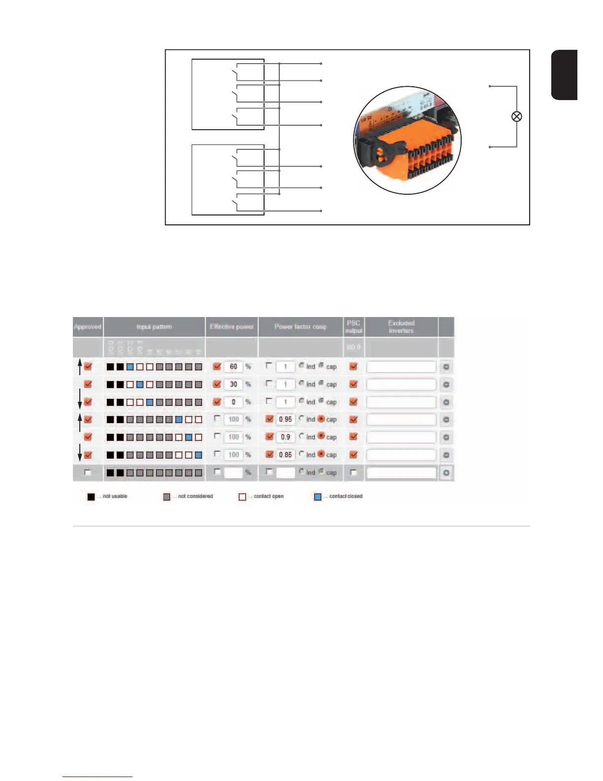
Settings on the UC Editor:
UC Editor – Dy-
namic Power Re-
duction
UCs or utility companies can prescribe feed-in limits for an inverter (e.g., max. 70% of the
kWp or max. 5 kW).
Dynamic power reduction takes into account self-consumption in the household before the
power of an inverter is reduced:
- An individual limit can be set.
- A counter for determining self-consumption per S0 can be connected directly to the
inverter (Fronius Galvo and Fronius Symo only).
- A Fronius Smart Meter can be connected to Fronius Datamanager 2.0 at the D-/D+
connections for Modbus data.
60 %
30 %
0 %
0,95
0,90
0,85
(1)
(2)
(4)
+
-
IO 2
IO 3
I 4
I 7
I 8
I 9
IO 0
(3)
(1)
(2)