16
6.3 Diagnostic panel
The Diagnostic Panel is a tool used to detect anomalies on FT5 inputs, outputs, sensors and actuators. In
order to access it, touch its icon at the main menu.
Information is split on 6 pages:
Page 1: general engine information;
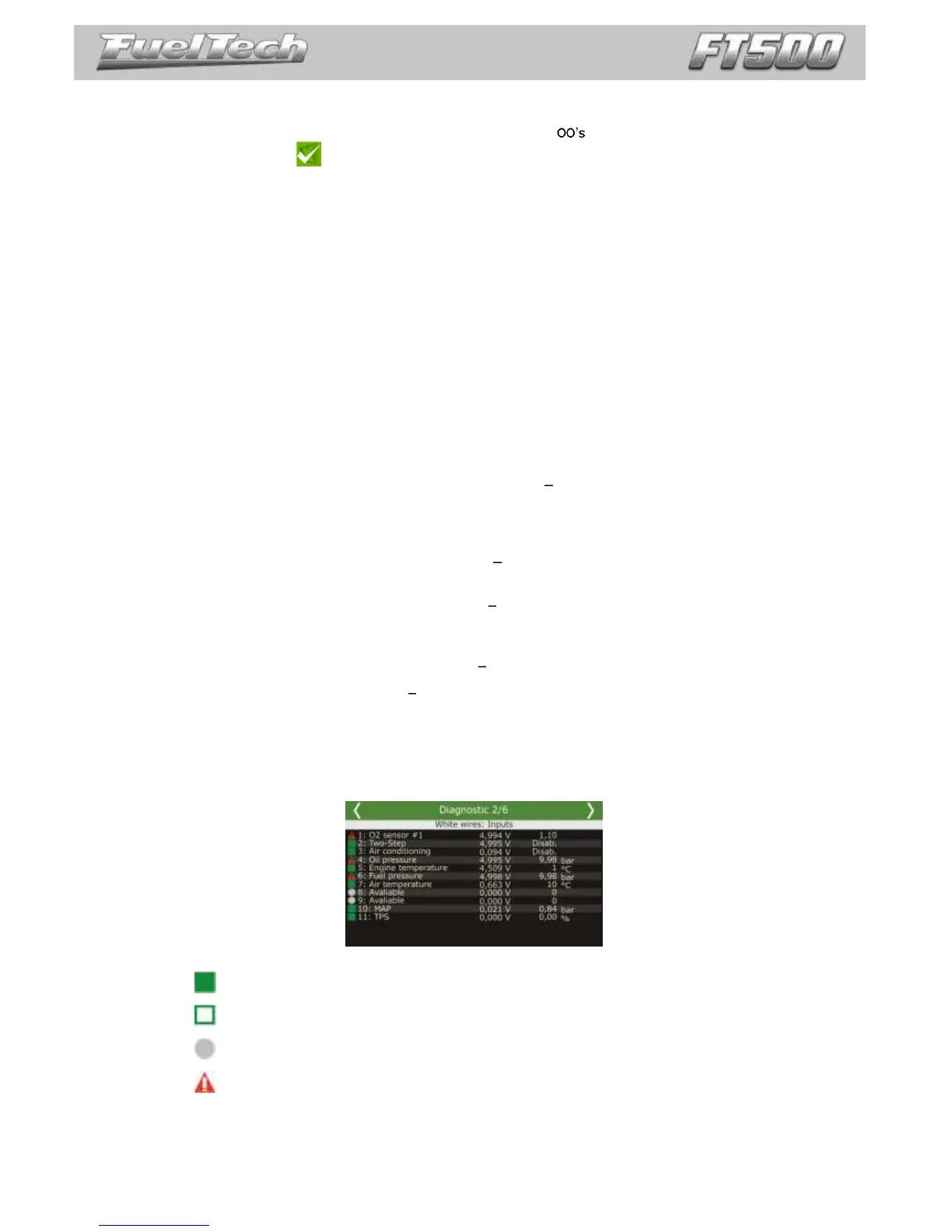
Page 2: status of white inputs;
Page 3: status of blue inputs;
Page 4: status of gray inputs;
Page 5: status of yellow inputs.
Page 6: RPM reading diagnostics.
Pages 2 to 5 shows input/output at the left column, position/command sent to the actuator, (outputs)/voltage
read (inputs) at the central column and the main information used to calculate the position/command at the right column.
For a thermatic fan output, i.e., diagnostic panel shows its status at the center column and the engine coolant
temperature at the right column.
On page 6 are information regarding the engine RPM signal readings. Below are some common erros and
possible causes:
Crank trigger error: gap detected at the wrong spot it detected the gap (missing teeth) in the wrong
place; it can also happen with a trigger wheel without missing tooth when there is a cam sync signal in
the wrong place. Also occurs in engines with a very light flywheel that accelerates and decelerates quickly
during compression strokes at engine startup and running.
Crank trigger error: wrong number of teeth number of teeth is different on the crank trigger wheel
than what is set at ECU. Electrical noise can cause a reading of a "ghost" tooth, for example.
Crank trigger error: missed tooth reading the ECU detected less teeth then it should have. Also
happens in engines with a very light flywheel that accelerate and decelerate very fast during compression
strokes at engine startup and running.
Crank trigger error: abnormal acceleration tooth error detection. Usually caused by signal noise.
Cam sync sensor: signal noise cam sync signal detected in the wrong spot. Typically this error is
caused when the ECU detects noise in the cam sync sensor signal or when the cam trigger wheel has
more than one tooth.
ATTENTION: when the 2-step and 3-step are set to activate by speed, its operation can be checked
through the page 1 of the Diagnostic Panel, not through page 2, since you are not using an analog input
(white wire) to switch
Diagnostic panel labels
Input or output is configured, enabled and working properly.
Input or output is configured and disabled.
Input or output has not been set up.
Input or output is set up, but there is an abnormal behavior.