46
15 Electronic throttle control
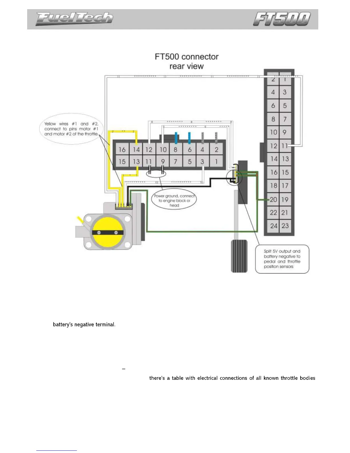
Electrical installation of an electronic throttle on FT500 is pretty simple. Check the example diagram below:
Yellow #1 wire (pin 13 of the 16-way connector) must be connected to the throttle input corresponding to the
Motor 1 input.
Yellow #2 wire (pin 14 of the 16-way connector) must be connected to the throttle input corresponding to the
Motor 1 input.
Green/red wire (24-way connector) is and 5V output used to feed throttle and pedal position sensors. It must be
spliced and connected to both of them.
Sensors negative can also be spliced between pedal and throttle position sensors. Connect it directly to the
White numbered wires are sensors signal inputs, connect them to the signal outputs of the pedal (Pedal 1 and
Pedal 2) and throttle (TPS1 and TPS2). After connecting these inputs, it is necessary to calibrate throttle and
pedal as guides chapter 16.1.
Pins 15 and 16 (16-way connector), yellow wires, will not be used for electronic throttle control, they can be set
up as auxiliary outputs.
15.1 Connection table throttle bodies and pedals
On the flash drive provided with FT500
and pedals. This table is also available for download in our website (check back because this table is frequently updated).
With the electrical connections ready, go back to chapter 7.5 and insert the throttle code (FT Number) that you
found on the throttle table connection.
If your throttle is not listed in our table, it might be necessary to send it to our tech team to have them check
compatibility and research its control parameters. In this case please contact our tech support.