31
11 Fuel injectors
FT500 has 8 outputs to control fuel injectors (blue wires #1 to #8). Each one of them can control up to 6
injectors with internal resistance above 10 Ohms (saturated injectors) or up to 4 injectors with internal resistance above 7
Ohms. Using a Peak and Hold driver, this capacity varies according to the output and the Peak and Hold current control
(2A/0,5A, 4A/1A or 8A/2A).
In situations where more than 8 outputs are needed, the gray or yellow outputs can be set as injector outputs. In
this case, the use of a Peak and Hold driver for these outputs is mandatory.
Injectors can be triggered in multipoint, semi sequential or sequential modes.
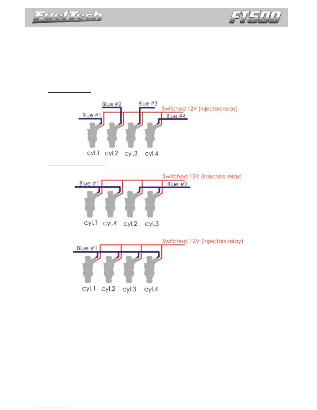
Examples of 4-cyl engines running high impedance injectors
Individual triggering: each blue output controls a cylinder. This is the most recommended connection cause is the
only one that allows individual per cylinder fuel and ignition compensations, amongst other functions.
Two injectors per channel: blue output #1 controls injector of cylinders 1 and 4. Blue output #2 controls
injectors of cylinders 2 and 3.
Four injectors per channel: use this connection only for compatibility with previous generation FT ECUs.
Even with each output controlling only one injector it is possible to change the triggering mode to multipoint
(batch fire), semi sequential (outputs triggered in pairs) or sequential.
NOTE: read chapter 4.3 before installing fuel injectors and wiring injector outputs.