43
14 Auxiliary outputs
The current capacity of these outputs is 0.7A, and therefore they
can drive solenoids or relays , the
installation of a fuse equivalent to the charge is recommended.
The auxiliary outputs have an overload protection system, with
automatic current cut-off. They trigger the charges (lamps, relays, etc.) with a
negative signal. Thus, the positive terminal must be connected to a switched
12V.
Each output must be configured in accordance to its function. For
more information about the outputs programming, see chapter 20. Note
that the configuration is not lost when the output is deactivated.
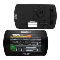
14.1 Cooling fan 1 and 2
adequate
The relay is switched by negative (sourced by the output), and the positive a switched 12V.
Important Note: the electric fan must not be connected directly to the auxiliary output without the use of a relay;
otherwise, the output will be damaged.
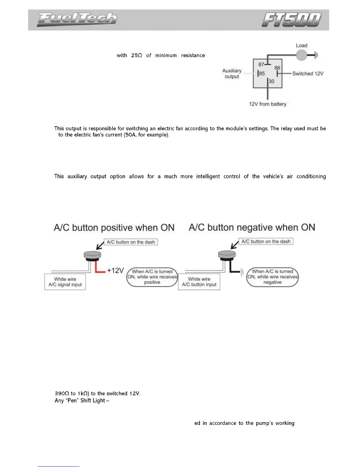
14.2 Air conditioning
compressor, as the ECU controls its activation only when the engine is already on and the idle speed has stabilized and
turns off the air conditioning when the valve exceeds a predetermined value (a resource commonly used in low-powered
engines).
In order to have the air conditioning control, the A/C button on the dashboard must be connected to a white
input of FT500. The two connection options are:
The air conditioning will remain turned on as long as the A/C Signal Input receives signal from the button. The
signal polarity can be chosen and it varies depending on the installation.
A/C compressor must be controlled with a relay, triggered by an auxiliary output (sends negative when activated).
NOTE: the auxiliary output that was setup as A/C will activate the A/C compressor relay and the A/C fan. For
more information on how to setup this output, check chapter 14.
14.3 Shift alert
This function activates an external shift light and works by sending negative when turned on. Any of the options
below can be used:
12V light bulb up to 5W: switched 12V directly connected to the light bulb and the negative connected to the
auxiliary output.
Light bulb over 5W: use a relay to switch the light bulb.
LED working as a Shift Light, which must be connected with a serial resistance (if used in 12V, resistance from
working in the same way as a light bulb.
14.4 Fuel pump
The fuel pump control must be done through a relay siz current. The
output sends out negative to activate the relay, which stays activated for 6 seconds and turns itself off if the ECU does
not receive any RPM signal. When the ECU reads RPM signal, it activates the fuel pump once again.