27
9 Electrical installation
As FT500 wires are fully configurable according to the installation needs, it is very important that the step by
step guide shown on chapter 5 is followed before starting the electrical installation. This way the wiring harness
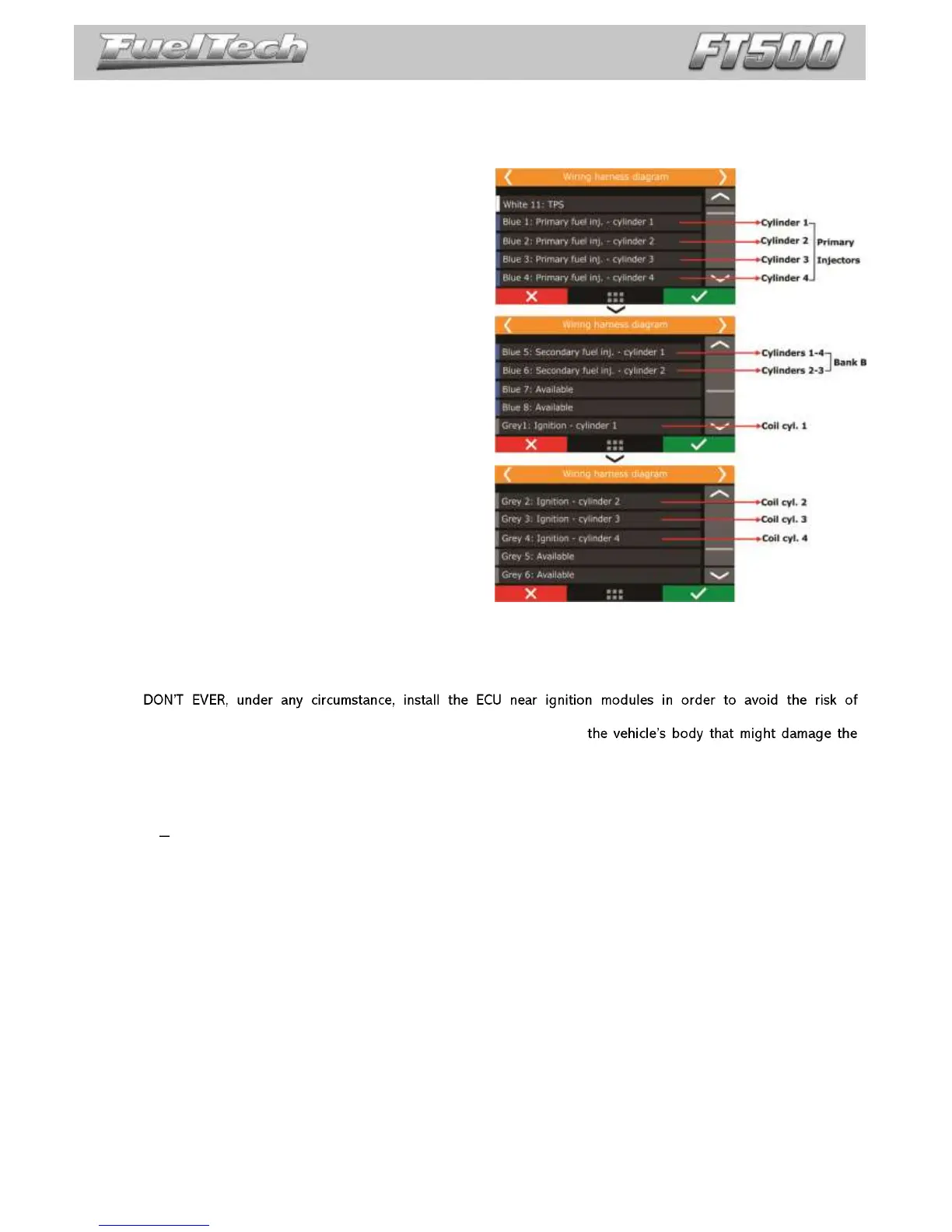
connection table is automatically filled as shows the example below:
Primary bank: 4 injectors on sequential mode (blue
wires #1 to #4)
Secondary bank: 4 injectors on semi sequential mode
(blue wires #5 to #6)
Ignition: coils are triggered individually, wasted spark
or sequential modes (gray wires #1 to #4)
Auxiliary outputs and sensors inputs: wires not used
for injectors or coils control can be set up as inputs or
outputs.
Based on this information, you can start the electrical installation that must be done with the ECU disconnected
from the harness and the battery disconnected from the vehicle. It is very important that the cable length is the shortest
as possible and that exceeding unused parts of wires are cut off.
Choose an appropriate location to affix the module inside the car, and avoid passing the cable wires close to the
ignition wires and cables, ignition coils and other sources of electric noise.
interferences.
Electric cables must be protected from contact with sharp edges on
wires and cause short circuit. Be particularly attentive to wires passing through holes, and use rubber
grommets/protectors or any other kind of protective material to prevent any damage to the wires. At the engine
compartment, pass the wires through places where they will not be subject to excessive heat and will not obstruct any
mobile parts in the engine.
Red wire 12V input
Being the 12V input to FuelTech ECU, this wire must be connected to 12V from a relay (Main Relay) and cannot be
shared with the positive wire that powers coils, fuel injectors or other actuators.
12V for fuel injectors: use a 14 AWG wire connected to a 40A relay. Protection fuse must be chosen according
to the peak current of the fuel injectors plus a 40% safety coefficient.
Example: for up to 4 injectors that draw 1A of current per injector on primary bank, and 4 injectors that
draw 4A of current per injector on secondary bank: (4x1A)+(4x4A)=20A + 40% = 28A. Use a 30A fuse.
12V for sensors: use a 24 AWG wire from the same 12V wire that feeds the ECU (Main Relay). Example: Hall
Effect sensors, pressure sensors, speed/RPM sensors, etc. This wire cannot be shared with the positive wire that
powers coils, fuel injectors or other actuators.
12V for coils, fuel pump and other high power actuators: use a wire with at least 14 AWG connected to a
relay and a fuse correctly dimensioned according to the actuator current draw. When using individual coils (COP),
it is recommended a 70A or 80A relay.
NEVER share the 12V that feeds injectors, coils or other accessories, because, after shutting the engine off, there is a risk
of reverse current that may damage a sensor or the ECU.