85
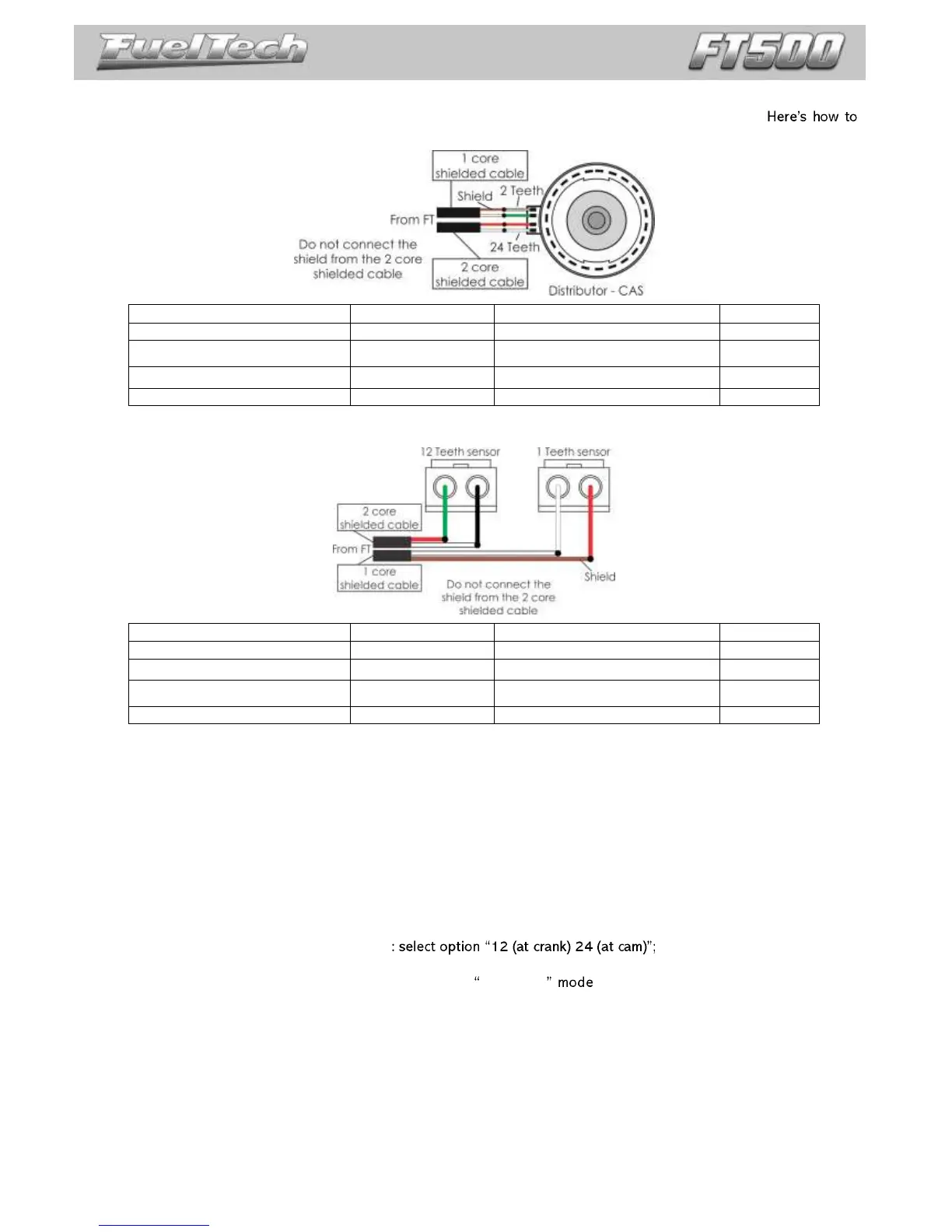
26.2 Crank angle sensor wiring
The stock distributor will be read by FT as a Crank Angle Sensor and Camshaft Position Sensor.
connect the FT to your stock Mazda distributor:
26.3 ECU setup
This setup is very important to correctly setup the ECU based on your engine. It is possible to do it by the ECU
screen, but, we strongly recommend you to use the FT Manager Software to go through this initial setup.
Below are only basic steps to rotary engines. Please, be sure to follow the step by step on chapter 7 to correctly
setup your ECU.
Under the RPM Signal menu, these are settings to rotary engines:
- RPM sensor: VR differential;
- RPM sensor edge: Falling edge (standard);
- Cam Sync Sensor: Variable reluctance (if experiencing electromagnetic interference, try selecting
the Hall Effect option);
- Cam Sync Polarity: Falling edge (standard);
- Crank Trigger Pattern
- Crank index position: 5°;
- Under advanced setup, select the Manual (B) under Sensor conditioning mode and set
the following voltage levels for RPM sensor and Cam sync sensor (only through the PC Software):
RPM Bias/Cam sync Bias: 2,49V;
Startup level: 1,00V;
RPM Peak/Cam sync Peak: 2,00V;
After that, make sure you go through chapter 7.3 and on to finish setting up Fuel injection, Pedal/Throttle and
Idle actuator menus according to your engine. After that, chapter 8 helps generating a default fuel and timing map for
your engine.