86
26.4 Ignition coils wiring
After setting everything up, the ignition outputs of the ECU are ready to be connected to your coils or ignition
modules. FT ECU ignition outputs cannot be connected directly to dumb coils, only to smart coils (coils with integrated
ignition module) or ignition modules.
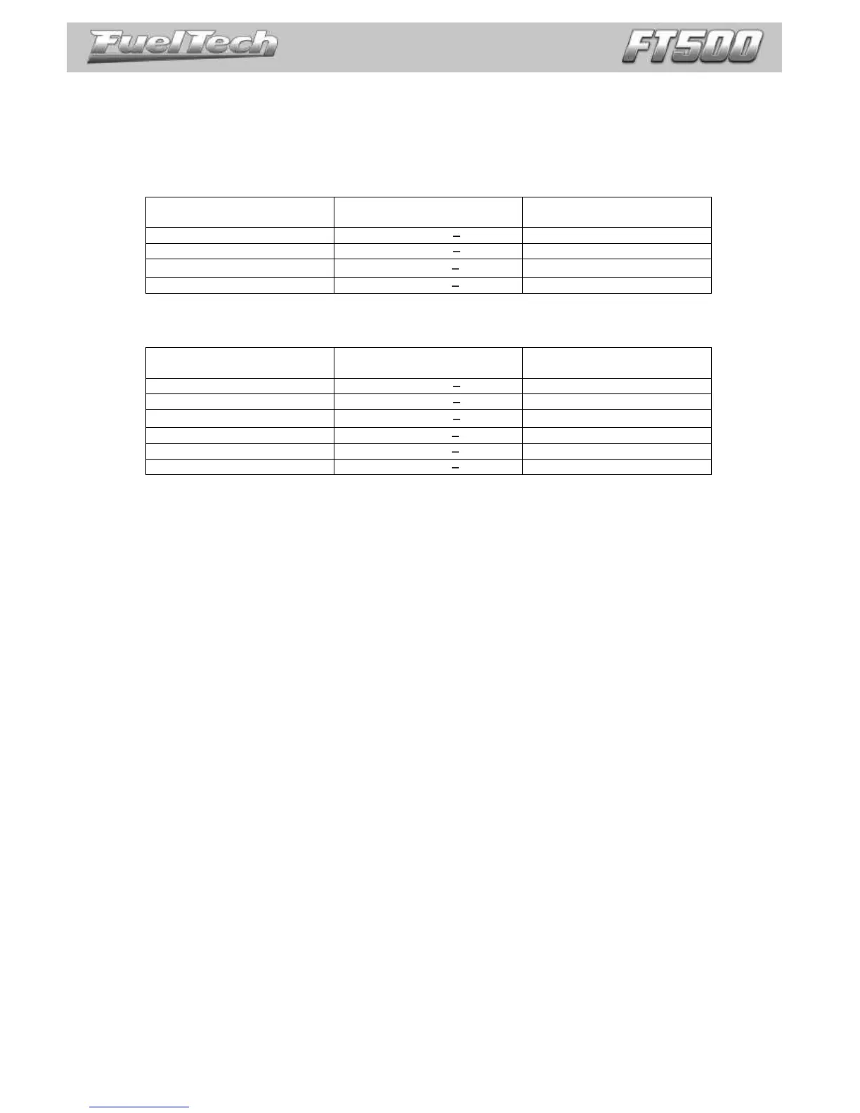
For 2 rotor engines, the gray wires are connected as the table below shows:
Recommended
SparkPRO-4 Channel
Trailing rotor #1 Coil T1
Trailing rotor #2 Coil T2
For 3 rotor engines, the gray wires are connected as the table below shows:
Recommended
SparkPRO-6 Channel
Trailing rotor #1 Coil T1
Trailing rotor #2 Coil T2
Trailing rotor #3 Coil T3
Please, make sure the correct ignition output wire of the ECU is connected to the corresponding ignition coil as
shows the table above. Also, be sure to check the wiring schematic on chapter 4.1 on this manual.