84
26 Rotary engines setup
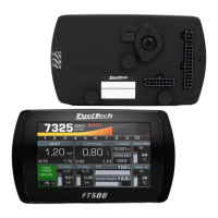
The crank angle sensor (CAS) has two (2) trigger wheels
that provide different signals to the ECU. As shown in picture, the
bottom wheel is a 24 teeth trigger that provides the RPM signal and
position of the eccentric shaft. The top wheel is a 2 teeth trigger
that provides information of the position of the rotor.
FuelTech ECU will control the ignition timing using the
reference of the 24 tooth wheel to spark the leading coil. All ignition
timing programmed in the tables is referenced to the leading coil.
Trailing coil will be fired using the programmed timing split
parameter. This means that if the ignition timing in the main table is
0° and timing split is 10 °, the ECU will fire the leading coil at 0°
and the trailing coil 10° after leading coil was fired.
26.1 Crank angle sensor installation and alignment
The Crank Angle Sensor needs to be installed in the engine at 0° (top dead center position). To align it, follow this
quick step by step:
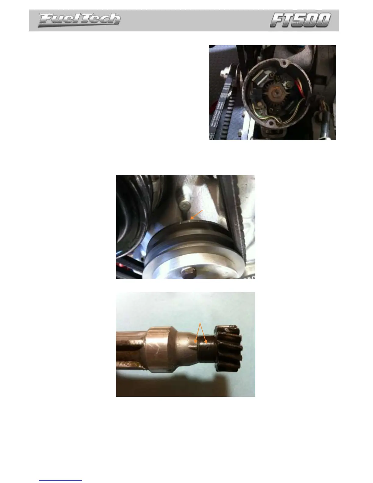
1. Use your ignition timing marks in the damper to align the eccentric to TDC. The ignition timing mark to be used is
shown below.
2. Align the Crank Angle Sensor to 0° using the mark in the shaft.
3. Install and tighten the Crank Angle Sensor in the engine. After the steps above are correctly followed, the Crank
Angle Sensor should be aligned at TDC with the eccentric shaft.