29
10 FT500 connection on previous FT installation
FT500 can be installed on vehicles that were already using older FT ECUs without the need to rewire everything.
However, a few points must be checked and changed.
The best option is to perform a new installation, with FT500 original harness, following the recommendations
contained on this guide. This eliminates any possibility of bad contact or electromagnetic interference, pretty common on
older installations.
WARNING: all the wire colors and numbers mentioned in this chapter are referred to FT400 main and aux
wiring harnesses.
10.1 Connection on an FT200, FT250, FT300, FT350 installation:
When using an installation originally done to one of these ECUs, it is mandatory that the 16-way harness is
installed. It has important power ground wires (black/white wires) that must be connected to the engine block/head. If
FT500 is powered without this harness, it can suffer serious damage, not covered by any kind of warranty.
Besides that, modifications shown below are also mandatory.
10.2 Connection on an FT400 installation:
As FT400 has the same connectors that FT500, (16 and 24-way), only
a few modifications are needed in order to make its harness fully compatible
with FT500.
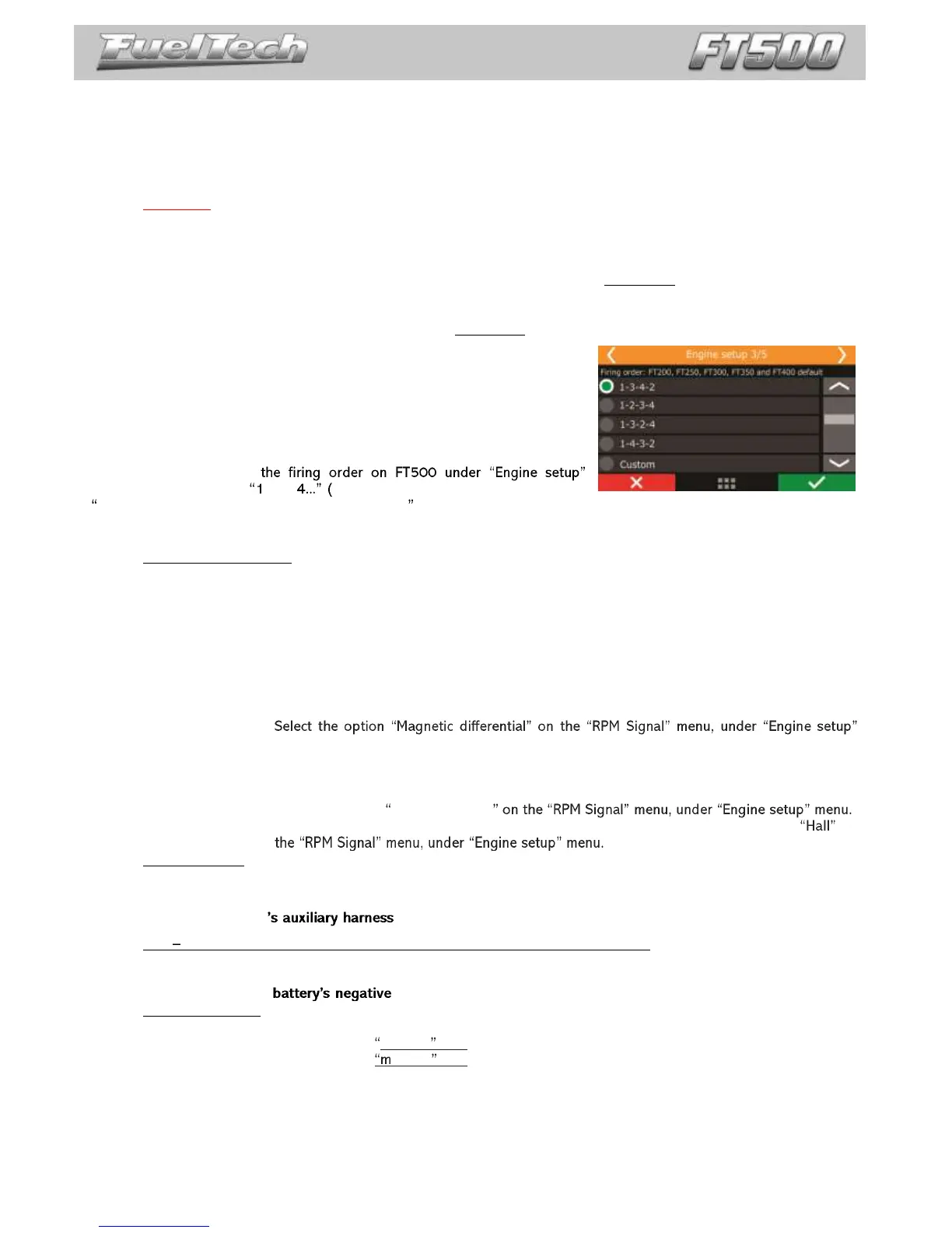
Firing order
When setting up
menu, select the option -2-3- At the top of the screen, the indication
FT200, FT250, FT300, FT350 and FT400 default is shown).
24-way connector (previous FTs Main harness)
Yellow wire #4 (pin 8): on FT500, this wire, that on FT400 had the function of an auxiliary output, is now the
RPM differential input. That`s why the recommendations below must be followed:
The function that was auxiliary output #4 must now be reallocated to yellow #7 of the 16-way connector
(any other output can be used). The connection of the wire that stays in the motor must be changed as
follows:
Yellow #4 must be connected in one of the ways shown below:
o Magnetic differential: that`s the most recommended option, cause makes the RPM sensor readings
most protected against electromagnetic interference.
Connect the yellow #4 wire on the pin where the shield (from the shielded cable) was
connected before. Now, the shield must remain disconnected.
menu.
o Magnetic simple: option used only to keep the harnesses compatible with fewer modifications on the
crank trigger sensor connections.
Leave yellow #4 wire disconnected;
Select the option Magnetic simple
Hall Effect sensor/distributor: leave yellow #4 disconnected and select the option on
Yellow/red wire: on FT500 this wire, that used to be the MAP analog output on FT400, is now an output used as
an injectors output (blue #3). By standard, MAP signal output is now on Orange #2 wire (pin 3) of the 16-way auxiliary
harness, but, it can be set up on any other output.
16-way connector (FT400 )
ETC ground output for throttle and pedal sensor (green/black wire, pin 11): on FT500 this wire is a power
ground input and must be connected to the engine block/head.
On FT400 this output is used as a ground for throttle and pedal sensors, so, change the wiring and connect
these sensors directly to the and connect the green/black wire to the engine block/head.
Electronic throttle: on FT400, electronic throttle control is done through 4 wires (brown/white 1 and 2 and
purple/white 1 and 2). On FT500, only two of them will be used:
-Brown/white #2 (pin 13) = motor 1 wire
-Purple/white #2 (pin 14) = otor 2 wire
Wire brown/white #1 (pin 15) and purple/white#1 (pin16) must be removed from the electronic throttle
connections. They can be used as auxiliary outputs (set up on the ECU first). On FT500 they are, respectively, the yellow
#3 (pin 15) and yellow #4 (pin 16) outputs.