75
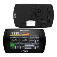
21.10 Time based speed (cut)
This feature is the same as the time based RPM (cut) but instead of use the engine RPM, it uses the wheel speed
(with a wheel speed sensor or by calculate speed) or the driveshaft RPM. It will perform ignition cut to keep the wheel
speed/driveshaft RPM under a predefined curve. Generally speaking, this speed/RPM control searches to limit the wheel
speed during the run.
The first screen will briefly explain how the feature works and it will ask what the speed reference is, if it is a
wheel speed or drive shaft RPM. You must have a wheel speed sensor or a driveshaft RPM sensor enabled to use this
feature.
The next screen is the wheel speed/driveshaft RPM versus time table. After the 2-step, every time the speed/RPM
goes above the curve, the ECU will perform ignition cuts.
The last screen will show the graph.
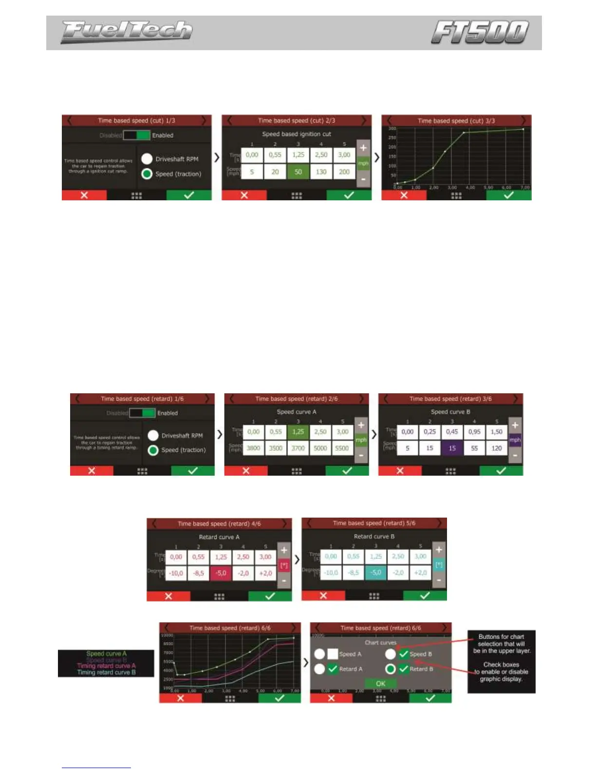
21.11 Time based speed (retard)
This feature reads the wheel speed (or the driveshaft RPM) and applies ignition compensation, according to the
two RPM curves (A and B) to control launch.
The basic idea is to retard the ignition timing, reducing power to the wheels. When the wheel speed reaches the
programmed in the "speed curve A", the ECU starts the programmed retard in the "delay curve A point".
As the speed increases, and goes toward the curve "B" speed, the retard applied to the timing (that is
interpolated between the two retard curves) is incremented. Thus, if the initial retard made by curve A is not sufficient to
hold the speed of the vehicle, the retard will increase as much as the RPM increase.
In cases where the speed/RPM exceeds the limits of the curve "B", the maximum retard (entered in curve B) will be
applied.
The first screen allows to select the speed/RPM reference (wheel speed or driveshaft RPM). You must have a
wheel speed sensor or a driveshaft RPM sensor enabled.
The next screens will show the speed/RPM curves A and B.
After this, the ignition retard curves A and B.
In the end, a graph will be displayed with all the curves (speed/RPM A and B, retard A and B)