EasyManua.ls Logo

Fueltec FT 500 User Manual

Fueltec FT 500
88 pages
To Next Page IconTo Next Page
Page #1 background imageLoading...
Page #1 background image
Programmable Electronic Fuel
Injection and Ignition System
Installation and
Operation Guide

Table of Contents

Question and Answer IconNeed help?

Do you have a question about the Fueltec FT 500 and is the answer not in the manual?

Fueltec FT 500 Specifications

General IconGeneral
BrandFueltec
ModelFT 500
CategoryAutomobile Electronics
LanguageEnglish

Summary

1 Presentation

4 Characteristics

4.1 Harness connections - 24 way connector

Details the pinout and function of the 24-way main harness connector.

Inputs and specifications

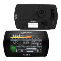
Lists all input and output specifications, processor, and operational parameters.

4.2 Harness connections - 16 way connector

Details the pinout and function of the 16-way auxiliary harness connector.

Functions

Details the operational functions and tuning capabilities of the FT500.

5 First steps with FT500 - read before installation

6 Getting to know the ECU

6.3 Diagnostic panel

Guide to the diagnostic panel for checking inputs, outputs, and sensors.

6.3 Diagnostic Panel

Guide to the diagnostic panel for checking inputs, outputs, and sensors.

7 Engine settings

7.1 Engine setup

Setting up engine type, cylinders, and limits like max RPM and boost.

7.2 RPM signal

Configuration of the RPM sensor input and type.

7.3 Ignition

Setup of ignition control modes, outputs, and dwell settings.

7.4 Fuel injection

Configuration of fuel injection modes, banks, and types.

7.5 Pedal/throttle

Setup and calibration for throttle position sensors and electronic throttle control.

7.7 Fuel injectors deadtime

Setting injector deadtime compensation for accurate fuel delivery.

7.8 Ignition Dwell

Configuration of ignition coil charging time (dwell) for optimal spark.

7.9 Wiring harness connection table

Reference table for ECU output wiring connections.

8 FuelTech base map

9 Electrical installation

Red wire - 12V input

Detailed instructions for connecting the 12V power input wire.

10 FT500 connection on previous FT installation

10.3 Ignition calibration

Procedure for calibrating ignition timing with distributors or crank triggers.

11 Fuel injectors

12 Ignition

13 Sensors and actuators

13.4 Throttle position sensor (TPS)

Setup and calibration for the throttle position sensor.

13.5 Crank trigger/RPM sensor

Installation and wiring for crank trigger and RPM sensors.

13.6 Camshaft position sensor

Installation and wiring for the camshaft position sensor.

14 Auxiliary outputs

14.7 Boost control

Setup for regulating engine boost pressure using a wastegate solenoid.

15 Electronic throttle control

4.1 Harness connections - 24 way connector

4.2 Harness connections - 16 way connector

4.3 Auxiliary outputs

RPM sensor

Cam sync sensor

7.3 Ignition

Ignition mode

Selecting ignition control modes: Distributor, Wasted Spark, Single Coil, Sequential.

Ignition output

Choosing the output signal edge for ignition control (e.g., Falling, Rising).

7.4 Fuel injection

7.5 Pedal/throttle

Electronic throttle control – ETC

Configuration and code insertion for electronic throttle systems.

Electronic throttle control motor outputs

7.7 Fuel injectors deadtime

7.8 Ignition Dwell

7.9 Wiring harness connection table

Black wire - battery's negative

Black/White wire - power ground

10.3 Ignition calibration

12.2 Ignition with crank trigger

Individual coils – electrical connections

Wiring for individual ignition coils connected to ECU outputs.

Wasted spark coils - electrical connections

Wiring for wasted spark ignition coil configurations.

Individual coils connections

Wasted spark coils connections

13.5 Crank trigger/RPM sensor

13.5.2 Crank trigger

Information on various crankshaft trigger wheel types and their alignment.

13.5.3 Crankshaft trigger sensor

Details on magnetic and Hall Effect crankshaft trigger sensors.

13.6 Camshaft position sensor

13.5.3 Crankshaft trigger sensor

14.7 Boost control

16 Sensors and Calibration

16.1 TPS calibration

Procedure for calibrating the throttle position sensor (TPS) for idle and wide-open throttle.

16.2 Electronic throttle/pedal calibration

Calibration process for electronic throttle and pedal position sensors.

16.10 Gear detection

17 Starting the engine for the first time

17.1 First engine start

Procedure for the initial engine start and checks.

17.2 Ignition calibration

Crucial step to calibrate ignition timing for accurate engine operation.

Calibration of the Crank Angle Sensor Ignition Timing

18 Fuel tables adjust

18.1 Main fuel table

Editing the main fuel injection map in basic or advanced mode.

18.2 Overall fuel trim

Applying a global percentage adjustment to the fuel map.

18.3 RPM compensation

18.4 O2 Closed Loop

18.6 Acceleration fuel enrichment and decay

18.7 Engine temperature compensation

18.8 Intake air temperature compensation

18.9 Battery voltage compensation

18.10 MAP / TPS compensation

18.11 Prime cranking pulse

18.12 Engine start

18.13 Post-start enrichment

18.14 Individual cylinder trim

18.15 Rotor compensation

19 Ignition tables adjust

19.1 Main ignition table

Editing the main ignition timing map in 2D or 3D.

19.3 MAP/TPS compensation

19.4 Engine temperature compensation

19.5 Intake air temperature compensation

19.7 Individual cylinder trim

19.8 Rotor compensation

19.9 Timing limits

20.2 Idle speed control

20.3 Deceleration cut-off

20.4 Revolution limiter

20.11 Boost control

21 Drag race features

21.3 2-step rev limiter

21.8 Time based revolution limiter

21.9 Time based RPM (retard)

21.10 Time based speed (cut)

21.11 Time based speed (retard)

21.12 Pro-Nitrous

24 Interface settings

25 File manager

25.1 FuelTech base map generator

Function to generate a base map for initial engine tuning.

26 Rotary engines setup

26.1 Crank angle sensor installation and alignment

Proper installation and alignment of the crank angle sensor on rotary engines.

26.2 Crank angle sensor wiring

26.3 ECU setup

26.4 Ignition coils wiring

27 FT500 - electrical diagram

27.2 FT500 – 4 cylinders - sequential fuel - SparkPRO-4 - coil-on-plug

27.3 FT500 – 2 rotors – sequential fuel - SparkPRO-4